
A well that starts producing sand can look deceptively healthy at first. Fluids are reaching the surface, the tubing may still be flowing, and production targets may appear achievable. Then the warning signs emerge: abrasive solids in separators, unstable rates, rising pressure losses, damaged valves, or an unexpected restriction downhole.
For field teams, sand production is not merely a housekeeping issue. It can turn a productive completion into a source of equipment damage, lost uptime, safety exposure, and expensive interventions. Yet aggressively restricting a well to stop sand can also leave valuable production underground.
That tension defines sand management: operators need to keep the formation stable enough to produce safely while preserving as much flow capacity as the reservoir and completion can support. The best answer is rarely a single tool; it is a decision process based on rock behavior, stress, fluids, completion design, and surveillance.
Understanding why sand moves, how to recognize the early signals, and how each control method affects productivity helps engineers make better trade-offs before a small solids problem becomes a major well-integrity event.
🪨 What Sand Production Actually Means
Sand production is the unwanted movement of formation grains from the reservoir into the wellbore and, potentially, to surface facilities. The solids may be quartz-rich sand, weakly cemented grains, fines, shale fragments, or fragments of damaged material near the wellbore.
Not every grain observed at surface indicates a severe failure. Small, short-lived volumes can occur during cleanup after drilling or stimulation. Sustained or increasing solids production, however, suggests that the formation around the completion is losing its ability to remain intact under flowing conditions.
⚖️ Why a Few Grains Can Become a Major Problem
Produced sand acts like an abrasive slurry. At high velocity, particles can erode chokes, elbows, valves, pumps, flowlines, and separator internals. Erosion can thin pressure-containing equipment and create integrity risks long before the damage is obvious externally.
Sand can also settle where velocity falls, such as in low spots, perforation tunnels, tubing, or wellbore deviations. Accumulation reduces flow area, raises pressure drop, and may ultimately obstruct the well. The commercial impact is therefore both direct equipment damage and deferred production.
🌍 Why Weak Reservoir Rock Fails Near a Well
Before drilling, the grains in a reservoir are supported by the rock framework and by stresses acting within the formation. Producing a well changes that balance. As pore pressure declines near the wellbore, the effective stress carried by the rock skeleton increases.
If the rock is poorly consolidated, naturally fractured, mechanically damaged, or exposed to unfavorable stress changes, grains can detach. Flowing fluids then provide the drag force that transports those grains toward the wellbore.
Think of a compacted sandcastle with water draining through it. As the water flow increases and the supporting moisture changes, weak sections can crumble. Reservoir rock is far more complex, but the basic interaction between strength, stress, and flow is similar.
📉 Drawdown: The Main Operating Lever
Drawdown is the difference between reservoir pressure and flowing pressure at the sandface. Increasing drawdown usually increases production rate, but it also raises fluid velocity and pressure gradients close to the well.
Those stronger gradients increase the force trying to pull grains into the completion. A well can therefore be stable at one flowing bottomhole pressure and produce sand after a modest rate increase, especially when the near-wellbore rock has already been weakened.
This is why sand control cannot be separated from production management. The allowable rate is often a geomechanical limit, not simply a surface-facility limit.
🧱 Rock Strength Is More Than Grain Size
Engineers sometimes associate sand risk only with unconsolidated sands, but grain size alone does not determine whether a formation will produce solids. Cementation, clay content, sorting, mineral composition, porosity, stress history, and natural fractures all influence strength.
A coarse but well-cemented sandstone may remain stable at substantial drawdown. A fine-grained, weakly bonded formation may fail more easily. Core testing, logs, offset-well history, and geomechanical interpretation are used together because no single measurement fully describes sand-failure risk.
🧭 Stress Direction Shapes Completion Behavior
In-situ stresses are the natural stresses acting underground. Drilling a hole and perforating casing redistribute those stresses around the wellbore. The redistribution is not uniform, so some directions around the hole may be more prone to compressive failure or tensile damage than others.
Well trajectory matters. A vertical, deviated, or horizontal well intersects the stress field differently, which can affect borehole stability, perforation response, and the geometry of a failed zone. Completion design should therefore consider stress orientation rather than treating every interval as mechanically identical.
🔫 Perforations Can Be the First Weak Link
Perforations create flow paths through casing, cement, and damaged rock. They also concentrate flow into a limited number of tunnels. If only part of the perforated interval is effectively open, local velocity and drawdown near those active tunnels can be much higher than the average well rate suggests.
Poor cleanup, crushed zones around perforations, inadequate penetration, or uneven perforation distribution can intensify this effect. Perforation strategy is consequently part of sand management, not just a means of connecting the reservoir to the wellbore.
💧 Water Breakthrough Can Change the Sand Risk
A change in produced-water rate can alter both fluid flow and rock behavior. Water may mobilize clays or fines, reduce capillary forces that had helped retain particles, and increase the volume of fluid passing through a vulnerable interval.
The effect depends on mineralogy and brine chemistry. In clay-sensitive formations, an incompatible injected or completion fluid may cause swelling or dispersion, which can reduce permeability and release fine particles. Water production does not automatically cause sand, but a sudden water change deserves attention when solids also increase.
🧪 Fluid Chemistry Can Mobilize Fines
Fines migration refers to the movement of very small particles, often clays or mineral fragments, through pore spaces. These particles may plug pore throats farther into the formation or accumulate in screens and gravel packs.
Salinity, pH, fluid velocity, and ion composition can influence whether fines remain attached to grain surfaces. Compatibility testing and disciplined fluid handling help reduce avoidable damage, particularly during completion, stimulation, workover, and water-injection operations.
🌊 High-Velocity Flow Carries More Than Hydrocarbons
Once grains detach, transport depends on fluid velocity, particle size, density, well angle, and flow regime. In an upward vertical flow path, enough velocity may carry particles to surface. In deviated or horizontal sections, particles can settle along the low side and form beds.
That distinction matters operationally. A well that produces little visible sand at surface may still be accumulating solids downhole. Surface measurements must therefore be interpreted alongside changes in well performance and completion geometry.
🛢️ The Surface Sand Trap Is Not the Whole Answer
Desanders, sand jets, separators, and dedicated solids-handling equipment protect surface facilities and enable safe collection of produced material. They are valuable barriers, but they do not stabilize the formation or prevent downhole plugging.
A surface system should be sized for credible solids volumes and inspected for erosion, accumulation, and disposal requirements. Treating it as the only sand-management measure can allow a damaging downhole condition to continue unnoticed.
🔎 Early Warning Signs in Daily Operations
Sand problems often announce themselves through patterns rather than one dramatic signal. Operators should correlate surface observations with rate, choke position, water cut, pressures, temperature, and recent operational changes.
- Visible solids in samples, separators, or desanders
- Unexpected erosion of chokes, valves, or elbows
- Rising tubing pressure or declining rate at similar choke settings
- Erratic flow, slugging, or intermittent production after a rate increase
- Restricted access during wireline work or difficulty reaching planned depth
- Increasing vibration, noise, or solids-related pump wear
None of these indicators alone proves formation sanding. Together, they provide a stronger basis for diagnosis.
📏 Measuring Sand Requires Consistent Sampling
Sand monitoring can range from simple collection and weighing of solids to online acoustic or erosion-monitoring systems. The useful question is not only “how much sand appeared?” but also “under what operating conditions did it appear?”
Consistent sampling intervals, documented choke settings, and clear handling procedures make trends more reliable. A poorly collected sample can confuse scale, corrosion products, stimulation residue, and formation sand, leading to the wrong response.
🧠 Separate Formation Sand From Other Solids
Solids arriving at surface may originate from several sources: formation grains, proppant from hydraulic fracturing, scale, corrosion products, drilling debris, or remnants of completion fluids. Their appearance can overlap, but the mitigation differs substantially.
For example, lowering drawdown may help a mechanically failing formation but will not remove scale buildup. Laboratory examination, particle-size assessment, mineral identification where warranted, and a review of recent operations can prevent an expensive misdiagnosis.
📊 Predicting a Safe Operating Envelope
A sand-free operating envelope is a practical range of rates and flowing pressures expected to limit unacceptable solids production. It is commonly informed by rock-strength data, stress analysis, completion details, offset performance, and calibration with actual well behavior.
It should not be treated as a permanent, exact boundary. Reservoir depletion, water breakthrough, stimulation, and mechanical damage can change conditions. The envelope is most useful when updated as surveillance provides new evidence.
🚦 Rate Management Is Often the First Response
Reducing drawdown is frequently the fastest way to lower sand risk. This may involve choking back the well, moderating gas lift, adjusting artificial lift, or avoiding abrupt rate changes after shut-ins and startups.
The drawback is clear: less drawdown commonly means less immediate production. But controlled production can be economically superior to repeated shutdowns, damaged equipment, and a well that must later be recompleted. A stable rate is often more valuable than a brief high-rate peak.
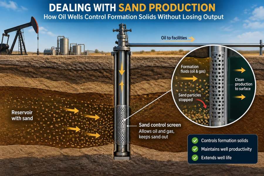
🧰 When Screens Provide Physical Retention
Standalone screens use a slotted or wire-wrapped barrier to retain formation solids while allowing reservoir fluids to enter. They are often applied where the formation can bridge against the screen and where completion conditions support effective placement.
Screen selection involves slot or aperture size, collapse resistance, erosion tolerance, flow area, and compatibility with the expected particle-size distribution. A screen that is too open can admit damaging solids; one that is too restrictive can plug or impose an unnecessary productivity penalty.
🏖️ Gravel Packs Build a Filter Around the Well
A gravel pack places carefully sized, high-permeability gravel around a screen. The gravel is designed to act as a filter between the formation and the screen, retaining formation sand while providing a broad flow path.
Gravel packing can be highly effective in weak, unconsolidated formations, but execution quality matters. Incomplete pack placement, contamination, poor fluid design, or gaps around the screen can create localized flow paths and reduce performance.
🧩 Openhole and cased-hole applications
In cased-hole gravel packs, perforations connect the formation to the gravel pack. In openhole gravel packs, the assembly is placed across an uncased reservoir interval. Each approach has different risks related to hole condition, zonal isolation, placement, and future intervention access.
🕳️ Expandable Screens Fit Specific Challenges
Expandable sand screens are run into open hole and expanded to contact or closely conform to the borehole wall. This can reduce the annular space where solids might accumulate and may be useful where conventional gravel placement is difficult.
They are not a universal substitute for gravel packs. Hole enlargement, washouts, mechanical damage during expansion, and uncertain contact in irregular formations can affect performance. Candidate selection depends heavily on borehole condition and operational experience.
🧱 Resin Consolidation Tries to Strengthen the Rock
Chemical consolidation treatments aim to bind formation grains near the wellbore using resin or other consolidating systems. The goal is to improve grain-to-grain strength while retaining enough permeability for fluid flow.
This approach can be attractive in selected intervals where mechanical exclusion is impractical. Its limitations include placement control, treatment penetration, compatibility, curing behavior, and the risk of reducing permeability if the treatment is poorly designed. Laboratory testing and careful execution are essential.
💥 Stimulation Can Help or Hurt Sand Control
Acidizing or hydraulic fracturing may bypass damage and increase productivity, but stimulation can also alter stresses, expose weak material, mobilize fines, or create high-conductivity paths that concentrate flow. The sand-control consequences must be evaluated before treatment design.
In a fractured well, proppant flowback is a separate concern from formation sand production. Flowback procedures commonly use controlled cleanup to avoid pulling proppant or weak formation material into the well too aggressively during the early production period.
⚙️ Artificial Lift Changes the Flowing Conditions
Artificial lift lowers flowing bottomhole pressure or moves fluids more efficiently to surface. This can restore production, but it may also increase drawdown beyond the formation’s stable limit. The lift system and sand-management strategy must be designed together.
Electric submersible pumps, rod pumps, gas lift, and progressing cavity pumps respond differently to solids. Some tolerate particular solids conditions better than others, but no system is immune to abrasion, deposition, or plugging. Placement, operating speed, and solids handling all matter.
🪜 Deviated and Horizontal Wells Need Special Attention
Long horizontal intervals increase reservoir contact and can reduce local inflow intensity, which may help in some cases. At the same time, they make solids transport more difficult because particles settle along the low side of the wellbore.
Uneven inflow can also concentrate drawdown near the heel or in high-permeability streaks. Inflow-control devices, completion segmentation, and careful cleanup planning may be needed to avoid localized sanding and accumulation.
🛑 Shut-Ins and Restarts Can Trigger Instability
Shutting in a well changes pressure and temperature conditions. During a restart, rapid drawdown can create transient forces that differ from normal steady-state production. Sand or proppant that settled during the shut-in may also be mobilized suddenly.
A controlled restart sequence, with staged choke changes and close monitoring, reduces the chance of shocking a vulnerable completion. This is especially relevant after long shut-ins, workovers, stimulation, or changes to artificial lift.
🧯 Erosion Management Protects the Rest of the System
Even when some solids production is accepted, the flow path must be managed to limit erosion. High-risk locations include restrictions, changes in direction, control valves, choke bodies, and areas where gas-rich flow accelerates particles.
- Use erosion-resistant materials where conditions justify them.
- Reduce unnecessary velocity through sensible piping and choke design.
- Inspect known high-risk components on a condition-based schedule.
- Monitor pressure containment, wall thickness, and equipment performance.
These controls do not replace downhole sand control, but they provide essential protection when complete elimination of solids is unrealistic.
🧾 A Practical Diagnostic Workflow
When sand appears, avoid reacting only to the latest sample. Start by confirming the solids source and building a timeline: when did the issue begin, what changed in rates or pressures, and what interventions occurred beforehand?
- Verify that collected solids are representative and identify likely origin.
- Compare solids trends with drawdown, water production, gas rate, and choke changes.
- Review completion diagrams, perforated intervals, stimulation history, and well trajectory.
- Assess immediate integrity and erosion risks before pursuing production optimization.
- Test a controlled operational change when safe, then evaluate the response.
- Select a longer-term completion or treatment option only after the failure mechanism is reasonably understood.
This workflow does not eliminate uncertainty, but it turns a reactive response into an evidence-based one.
🚫 Common Mistakes That Sacrifice Output or Integrity
One common mistake is choking back indefinitely without learning why the well sands. Rate reduction can be the correct short-term protection, but it should be paired with diagnosis and surveillance rather than becoming a substitute for a plan.
Another is selecting a screen, gravel pack, or chemical treatment from a standard template. Sand-control hardware that ignores particle size, rock strength, inflow distribution, and intervention constraints can fail even if installation appears successful.
Equally risky is increasing rate after a clean production test without monitoring solids. A well may cross its failure threshold only after a delayed change in stress, water production, or near-wellbore damage.
🤝 Sand Control Is a Multidisciplinary Decision
Reservoir engineers estimate deliverability and depletion behavior. Geomechanics specialists evaluate stress and rock failure. Completion engineers design the barrier or treatment, while production and facilities teams manage flow, erosion, and monitoring.
The strongest decisions connect these perspectives. A completion with excellent sand retention but unacceptable skin may disappoint commercially; a high-rate design that overlooks erosion and well integrity may create avoidable operational risk.
📈 How to Judge Success Beyond “No Sand Seen”
A successful strategy is not always one that produces zero measurable solids. In some operations, a small, controlled solids rate can be handled safely while maintaining better overall production. In others, even minor sand production is unacceptable because of subsea equipment, high-pressure service, or limited intervention options.
Performance should be judged against a defined objective: stable production, manageable erosion, no loss of well access, acceptable equipment condition, and a completion that remains serviceable over time. The acceptable threshold is asset-specific.
🧭 Choosing the Right Strategy for the Well
| Approach | Best suited to | Main advantage | Main limitation |
|---|---|---|---|
| Rate management | Early response or marginal sand risk | Fast and reversible | May reduce production materially |
| Standalone screen | Suitable formations with reliable bridging | Simple mechanical barrier | Can plug or admit fines if poorly selected |
| Gravel pack | Weak, unconsolidated formations | Robust filtration when well placed | Complex placement and potential productivity loss |
| Expandable screen | Selected openhole conditions | Reduces annular solids space | Sensitive to hole condition and installation |
| Chemical consolidation | Selected near-wellbore failures | Can strengthen formation locally | Placement and permeability risks |
No row in this table is a universal recommendation. The best option follows from the failure mechanism, well geometry, operational constraints, and the cost of future intervention.
✅ The Core Principle: Stabilize, Retain, and Monitor
Effective sand management follows three connected goals. First, stabilize the formation by keeping drawdown and fluid conditions within a tolerable range. Second, retain solids using an appropriate completion or treatment where production demands exceed what rate control alone can safely provide.
Third, monitor the well and facilities continuously enough to catch changes before erosion, plugging, or loss of access becomes severe. Sand control is not simply about blocking particles; it is about balancing rock stability, flow capacity, equipment protection, and long-term well value.
A well does not need to choose between uncontrolled sand production and unnecessary restriction. With sound diagnosis, disciplined operations, and a completion strategy matched to the reservoir, engineers can protect the well while preserving the production it was built to deliver. 🛢️🪨📈