
A mature oil field can look healthy from the surface: wells are still flowing, separators are operating, and production targets remain on the schedule. Yet beneath that routine, the reservoir may be losing the energy that once pushed fluids toward the wellbore.
The first warning is often subtle. A well needs more choke opening to deliver the same rate, flowing pressure declines, gas-oil ratio changes, or water production rises. Eventually, artificial lift is working harder simply to offset a reservoir that can no longer provide sufficient pressure support.
This is not merely a production problem. Lower reservoir pressure can change fluid behavior, reduce well deliverability, trigger sand production, complicate water handling, and leave substantial oil behind if the field response is poorly timed.
Managing pressure decline therefore requires more than adding pumps or drilling infill wells. It requires a connected understanding of reservoir energy, rock and fluid properties, well performance, surveillance data, economics, and operating risk.
🧭 What Reservoir Pressure Really Represents
Reservoir pressure is the force per unit area exerted by fluids in the pore spaces of subsurface rock. It is not a single fixed value across a field: pressure can vary by depth, compartment, fluid zone, and distance from producing wells.
In simple terms, it is part of the energy available to move oil, gas, and water through the reservoir and into a well. As fluids are withdrawn, that energy usually declines unless a natural or engineered mechanism replaces it.
⚙️ Why Mature Fields Lose Their Natural Drive
Production removes mass from the reservoir. If replacement fluids do not enter at a comparable volume and in the right locations, average pressure falls over time.
The rate and consequence of decline depend on the original drive mechanism. A reservoir with an active aquifer may receive water influx, while a solution-gas-drive reservoir often loses pressure more rapidly after gas comes out of solution.
- Oil and connate-water expansion provide limited early support.
- Gas-cap expansion can contribute energy if a gas cap exists and remains connected.
- Water influx may support pressure, but can also accelerate water production.
- Compaction can add energy in some formations, while creating geomechanical concerns.
📉 Pressure Depletion Is Not the Same as Production Decline
A falling oil rate does not automatically prove that reservoir pressure is falling. Production can decline because of scale, wax, water loading, pump limitations, liquid dropout, or increasing skin near the wellbore.
Conversely, a reservoir can experience pressure depletion while field oil rate is temporarily maintained through artificial lift or larger drawdown. Separating these effects is essential because the correct intervention depends on the limiting mechanism.
🧪 Start With Reliable Pressure Measurements
Pressure management begins with data quality. Static or stabilized pressure surveys, pressure-transient tests, permanent downhole gauges, and carefully interpreted flowing-pressure data each reveal different parts of the picture.
A measurement taken before the well has adequately shut in may reflect local pressure disturbance rather than average reservoir pressure. Gauge depth, fluid gradients, temperature effects, and datum correction also matter. A precise-looking number is not necessarily a representative number.
🗺️ Build a Pressure Map, Not Just a Field Average
An average field pressure can conceal major differences between fault blocks, layers, and patterns of injection and production. Pressure maps show whether wells share communication and where depletion is concentrated.
For example, a hypothetical field may appear moderately depleted on average, while one southern compartment has lost much more pressure because a sealing fault limits aquifer or injection-water support. Treating both areas identically would waste capital and may worsen imbalance.
🧱 Identify Compartments Before Designing Support
Faults, shale barriers, stratigraphic pinch-outs, cemented intervals, and low-permeability streaks can divide a reservoir into partially connected compartments. A pressure-support project succeeds only if injected fluid can reach the oil-bearing rock that needs support.
Connectivity is rarely a simple yes-or-no question. Two areas may communicate slowly enough that short-term pressure differences persist, yet still equilibrate over years. Reservoir models should represent that uncertainty rather than assume perfect communication.
🌊 Understand the Role of Aquifers
An aquifer is water-bearing rock that may be connected to the hydrocarbon reservoir. Its water can expand and move into the oil zone as pressure falls, providing a natural pressure-support mechanism.
A strong aquifer can delay depletion, but it does not guarantee high oil recovery. Water can reach producers early through high-permeability pathways, leaving less-swept oil behind. The practical goal is controlled displacement, not simply maximizing water movement.
💨 Watch for the Bubble-Point Transition
The bubble point is the pressure at which dissolved gas first evolves from oil at reservoir temperature. Above it, oil is undersaturated; below it, free gas can form in the reservoir.
Once pressure drops below bubble point, fluid flow becomes more complicated. Gas may help provide expansion energy, but it can also reduce oil relative permeability, increase gas-oil ratio, and accumulate near wellbores where high drawdown promotes gas liberation.
🫧 Free Gas Can Help and Harm Recovery
Gas expansion is a real source of reservoir energy, especially in solution-gas-drive systems. However, gas is mobile and tends to move through favorable pathways. If it reaches producers too quickly, it can bypass oil and reduce the effectiveness of the drive.
High produced gas rates may also consume surface compression capacity and constrain oil handling. Reinjecting gas, conserving produced gas, or controlling drawdown may be preferable to unrestricted gas production, depending on field conditions and facilities.
🪨 Relative Permeability Explains Many Surprises
Rock permeability describes how readily a rock transmits fluid, but multiphase reservoirs require relative permeability: the effective ability of oil, water, or gas to flow when the others are present.
As water saturation rises, water usually becomes easier to produce and oil becomes harder to move. As gas saturation rises above a critical level, gas becomes mobile and can compete with oil flow. Pressure support must therefore be evaluated alongside saturation changes, not in isolation.
🚰 Waterflooding as a Pressure-Support Tool
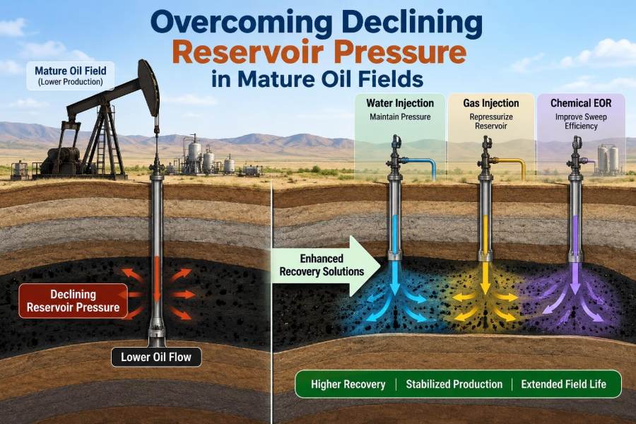
Waterflooding injects water into selected wells to replace produced volume, maintain pressure, and displace oil toward producers. It is one of the most established recovery methods because water is often available and injection systems can be scaled across a field.
Its effectiveness depends on injection quality, reservoir continuity, mobility ratio, pattern geometry, and surveillance. Simply injecting the largest possible volume can cause early breakthrough, fracture extension, or disposal constraints without improving ultimate recovery.
🔁 Balance Voidage Replacement
Voidage replacement compares injected reservoir volume with produced reservoir volume. It provides a useful operating indicator of whether the field is broadly replacing the pore volume vacated by produced fluids.
But fieldwide balance is not enough. An injection-heavy northern area cannot necessarily support depleted southern wells across a barrier. Engineers should examine voidage replacement by pattern, layer, and compartment whenever the data allow.
🎯 Design Injection Patterns Around Sweep
Injection patterns place injectors and producers in a planned arrangement, such as line-drive or five-spot configurations. Their purpose is to move the flood front through oil-bearing rock rather than allowing water to find one short route to a producer.
Existing mature fields rarely have ideal well locations. Pattern design may involve converting selected producers to injectors, drilling targeted infill wells, isolating layers, or changing rates to improve areal and vertical sweep.
📏 Injection Rate Has a Safe Operating Window
Too little injection may fail to arrest pressure decline. Too much injection can raise pressure beyond operating limits, cause unwanted fracture growth, force water into non-target intervals, or create early water breakthrough.
The safe window is defined by reservoir pressure, fracture pressure, well integrity, injectivity, facility capacity, and regulatory requirements. It should be reviewed as conditions evolve, not treated as a one-time design value.
🧯 Protect Well Integrity During Injection
Injection exposes tubing, packers, casing, cement, and wellheads to sustained pressure, corrosive fluids, and temperature changes. A loss of mechanical integrity can divert water behind casing or create an environmental and safety risk.
Pressure testing, annulus monitoring, corrosion management, cement evaluation where warranted, and clear maximum-pressure controls are fundamental. Reservoir optimization never justifies operating a well outside verified integrity limits.
🧂 Manage Water Quality and Compatibility
Injected water can contain suspended solids, bacteria, oxygen, incompatible ions, or residual oil. These can plug pore throats, promote corrosion, create scale, or reduce injectivity near the wellbore.
Compatibility testing should consider formation water, injected water, rock minerals, and anticipated pressure-temperature conditions. Filtration and chemical treatment are not generic add-ons; they are selected to address the actual source of impairment.
🧬 Polymer Flooding When Water Alone Is Too Mobile
In some reservoirs, injected water moves much more easily than oil. This unfavorable mobility ratio encourages channeling and poor sweep. Polymer added to injection water can increase water viscosity and improve the displacement front.
Polymer flooding is not automatically suitable for every mature field. Salinity, temperature, shear degradation, adsorption on rock, injectivity, facility modifications, and produced-water handling can all limit performance. Screening and pilot work are especially valuable.
🌫️ Gas Injection and Miscibility
Gas injection can support pressure, recycle produced gas, and under certain pressure-composition conditions improve oil displacement. Miscible injection occurs when injected gas and oil mix sufficiently to reduce interfacial tension and improve microscopic displacement.
Whether miscibility is feasible depends on oil composition, injected-gas composition, temperature, and pressure. Below the required conditions, gas may still provide an immiscible displacement benefit, but gravity segregation and gas channeling become central design concerns.
🧪 Chemical EOR Needs Careful Screening
Surfactants, alkaline formulations, and other chemical enhanced-oil-recovery methods aim to mobilize oil that remains trapped after conventional waterflooding. They can address residual oil at the pore scale, where pressure maintenance alone has limited reach.
These processes are sensitive to mineralogy, brine chemistry, temperature, adsorption, degradation, and logistics. A favorable laboratory result is only an early step; scale-up requires realistic core tests, simulation, facilities planning, and a disciplined pilot.
🛢️ Artificial Lift Complements, Not Replaces, Reservoir Management
Electric submersible pumps, gas lift, rod pumps, progressive cavity pumps, and hydraulic systems lower flowing bottomhole pressure so fluids can enter the well more easily. They can extend productive life when reservoir pressure is insufficient for natural flow.
However, artificial lift does not restore reservoir energy. Aggressively lowering bottomhole pressure may increase gas liberation, water coning, sanding, or water breakthrough. The best lift setting is the one that improves net value without damaging reservoir performance.
🕳️ Control Drawdown Near the Wellbore
Drawdown is the difference between reservoir pressure and flowing bottomhole pressure. It is the immediate driving force for production, but excessive drawdown can create local problems even when the average reservoir remains healthy.
Near wells with gas caps, bottom water, unconsolidated sand, or delicate completion intervals, high drawdown may pull unwanted fluids or solids into the well. Rate management, selective completions, and zonal isolation can be more effective than simply increasing lift capacity.
💧 Diagnose Water Breakthrough Correctly
Rising water cut may result from normal flood-front arrival, channeling through high-permeability streaks, fracture communication, behind-casing flow, coning, or an untreated layer in a commingled completion. Each mechanism needs a different response.
Useful diagnostic evidence includes production logs, tracer data, pressure behavior, saturation logs, well tests, and comparisons among offset wells. Treating every water increase with a generic shutoff treatment risks spending money without addressing the flow path.
🔬 Use Surveillance as a Closed-Loop Process
Effective reservoir management follows a loop: measure, interpret, act, and verify. Production rates alone are insufficient because they describe outcomes without always explaining the reservoir process causing them.
- Track pressures, rates, water cut, gas-oil ratio, injection volumes, and injection pressure.
- Compare actual behavior with reservoir-model forecasts and material-balance expectations.
- Investigate meaningful deviations promptly rather than averaging them away.
- Adjust rates, completions, lift, or injection allocation, then measure the response.
🧮 Material Balance Provides a Reality Check
Material balance relates production, pressure change, fluid expansion, water influx, and injected volumes. It is a reservoir-scale accounting framework that helps identify the dominant energy sources and whether observed depletion is plausible.
It is most useful when pressure and fluid-property data are representative. Poor pressure data, uncertain PVT properties, or unrecognized compartments can produce misleading conclusions, so material balance should be integrated with geology, well tests, and dynamic simulation.
🖥️ Reservoir Simulation Tests Competing Strategies
A dynamic reservoir simulation model represents fluid flow through a geological framework over time. It can test alternative injection locations, rate limits, well conversions, gas recycling, or infill drilling before major capital is committed.
A model is not a crystal ball. Its value comes from history matching key observations and explicitly testing uncertainty ranges. A simple, well-calibrated model can be more useful than a highly detailed model built on assumptions that cannot be verified.
💰 Choose Interventions by Incremental Value
A technically promising option may still be uneconomic if it requires extensive water treatment, compression, new pipelines, workovers, or long lead times. Decision-making should compare incremental oil, operating cost, capital cost, energy use, emissions implications, and execution risk.
Timing matters. Early pressure support can protect recovery, while late intervention may have less oil left to mobilize. Yet acting too early without adequate reservoir understanding can lock the asset into an expensive and poorly targeted scheme.
🌍 Account for Energy, Emissions, and Water Constraints
Water injection, produced-water treatment, gas compression, pumping, and chemical handling all require energy and infrastructure. Mature-field optimization should therefore consider the full operating system, not only barrels at the wellhead.
Produced-water volumes can grow significantly as fields mature. Reuse for injection may reduce disposal demand where technically suitable, but water chemistry, treatment requirements, storage, and integrity controls still determine whether reuse is practical.
👷 Coordinate Reservoir, Production, and Facilities Teams
Pressure decline crosses discipline boundaries. Reservoir engineers interpret subsurface energy; production engineers manage wells and lift; geoscientists define connectivity; facilities teams handle water, gas, and injection capacity; integrity specialists protect containment.
A rate increase proposed by one team can affect separation, water treatment, compression, injection limits, and reservoir sweep. Shared forecasts, common assumptions, and regular exception reviews prevent local optimizations from harming fieldwide performance.
⚠️ Common Mistakes in Pressure-Decline Response
Several recurring mistakes can make a mature-field problem harder to solve:
- Chasing oil rate only: increasing drawdown without checking gas, water, sand, or coning risk.
- Using field averages blindly: overlooking compartments and layer-level pressure differences.
- Equating injection volume with recovery: ignoring where injected fluid actually travels.
- Delaying surveillance: discovering breakthrough or injectivity loss after it becomes expensive to reverse.
- Skipping pilots: scaling an EOR concept before uncertainty has been narrowed.
🧩 A Practical Response Sequence
When pressure decline becomes material, a disciplined sequence is more reliable than selecting a technology first. Begin by validating pressure, rate, fluid, and completion data; then define whether the limitation is reservoir energy, connectivity, well productivity, facilities, or a combination.
Next, rank options from operational adjustments to targeted workovers, injection redistribution, new injectors, artificial-lift optimization, and recovery-process pilots. Set measurable success criteria in advance, such as stabilized pressure in a compartment, improved injectivity, delayed water breakthrough, or sustained incremental oil.
🔮 Plan for the Late-Life Reservoir, Not Yesterday’s Field
As a field ages, the dominant challenge may shift from oil deliverability to water handling, lift reliability, integrity, or declining economic margin. Pressure management should evolve with that changing operating envelope.
Late-life plans benefit from scenario thinking: what happens if injectivity declines, an injector fails, water treatment becomes constrained, or a compartment depletes faster than expected? Preparing contingencies is often less costly than reacting after production is already lost.
🏁 The Core Principle: Manage Energy and Flow Paths Together
Declining pressure is not solved by a single piece of equipment or one universal recovery method. Pressure support works when the injected or conserved energy reaches the intended reservoir volume and displaces oil along useful flow paths.
The strongest mature-field strategies combine representative surveillance, realistic reservoir understanding, controlled drawdown, fit-for-purpose injection, sound well integrity, and economic discipline. They treat the reservoir and surface system as one connected operating system.
In mature oil fields, the goal is not simply to raise pressure—it is to manage reservoir energy and fluid movement so that more oil is recovered safely, reliably, and with clear economic purpose. 🛢️📈🌍