
A well can look productive on the day it is completed and still need help later in its life. At first, natural reservoir pressure may be enough to push fluids up the tubing and into surface equipment. Over time, that pressure commonly declines, while water production, fluid weight, and flow resistance can all increase.
That is when a well may stop flowing at an economic rate even though valuable hydrocarbons remain in the reservoir. The oil has not necessarily disappeared; the well simply lacks enough energy to carry it to the surface efficiently.
Artificial lift supplies or transfers energy to the produced fluids so they can travel from the producing formation to the surface. It is one of the most practical links between a reservoir’s remaining potential and actual daily production.
For students, artificial lift connects reservoir engineering, production engineering, equipment design, power systems, and field operations. For working professionals, it is a continuous optimization problem: select the right method, operate it within limits, recognize failure signals early, and adapt as well conditions change.
🧭 What Artificial Lift Actually Means
Artificial lift is a broad term for methods that reduce the pressure burden on a producing reservoir or add energy to the fluid column in a well. Despite the name, it does not “create” oil or increase the amount originally in place.
Instead, it changes the flowing conditions so the reservoir can deliver fluids at a useful rate. A pump may raise pressure, gas injection may lighten the fluid column, or a surface-driven system may mechanically lift liquid upward.
Artificial lift is distinct from enhanced oil recovery. EOR changes displacement or sweep within the reservoir, while artificial lift mainly helps produced fluids move through the wellbore.
📉 Why Wells Stop Flowing Naturally
A naturally flowing well depends on reservoir pressure being greater than the pressure needed to move fluids through the formation, perforations, tubing, choke, flowline, and surface facilities. This pressure requirement is often called the total system backpressure.
As a field matures, reservoir pressure generally falls. Water may enter the produced stream, increasing the average density of the fluid column. Gas behavior can also change, affecting flow stability and friction.
Near-wellbore damage, scale, wax, solids, undersized tubing, and restrictive surface equipment can add resistance. Artificial lift cannot solve every one of these problems, but it can be designed around realistic pressure and fluid conditions after restrictions are identified.
⚖️ The Pressure Balance Behind Production
Think of a producing well as a pressure balance. The reservoir provides pressure energy; the production system consumes it through hydrostatic head, friction, acceleration, and surface backpressure.
Hydrostatic head is often the dominant load in a liquid-producing well. It is the pressure caused by the weight of fluid in the vertical column. A dense water-rich column requires substantially more pressure support than a lighter oil-and-gas mixture.
Artificial lift changes that balance. A downhole pump can raise fluid pressure, while gas lift lowers mixture density and can reduce the hydrostatic pressure that the reservoir must overcome.
🧪 The Role of Inflow and Outflow Performance
Lift selection begins with two related relationships. Inflow performance describes how much fluid the reservoir can deliver into the well at a given flowing bottomhole pressure. Outflow performance describes the pressure required to move that fluid to the surface.
Production is possible where these relationships intersect. If the required outflow pressure is too high, the well’s operating rate is low or the well cannot flow.
Artificial lift aims to shift the outflow requirement downward or increase pressure along the flow path. Engineers use well tests, fluid properties, pressure measurements, and production history to estimate these relationships. The models are useful, but they must be updated when water cut, gas-oil ratio, tubing condition, or reservoir behavior changes.
🔄 The Main Families of Artificial Lift
Most field applications fall into five major categories: sucker-rod pumping, electric submersible pumping, gas lift, progressive cavity pumping, and hydraulic pumping. Each transfers energy differently and has a different operating envelope.
| Method | Primary energy mechanism | Often suited to |
|---|---|---|
| Sucker-rod pump | Reciprocating downhole pump driven from surface | Moderate liquid rates and many conventional wells |
| ESP | Multistage centrifugal pump powered electrically | High liquid-rate wells |
| Gas lift | Injected gas reduces fluid density and supports flow | Deviated wells and variable operating conditions |
| PCP | Rotating positive-displacement pump | Viscous fluids and solids-prone service |
| Hydraulic pump | Power fluid drives a downhole pumping unit | Selected deep, deviated, or specialized applications |
No method is automatically “best.” The correct choice depends on expected production rate, depth, fluid composition, deviation, solids, available power or gas, intervention costs, and facility constraints.
🐴 Sucker-Rod Pumping: The Familiar Pumpjack
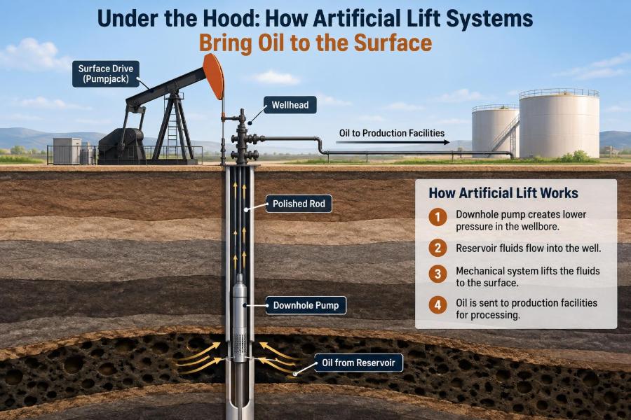
Sucker-rod pumping is the system many people picture when they think of oil production. A surface pumping unit converts rotating motor motion into vertical reciprocating motion, moving a string of steel or fiberglass rods.
The rods operate a downhole reciprocating pump, usually placed below the dynamic fluid level. On the upstroke and downstroke, traveling and standing valves open and close in sequence, allowing liquid to enter the pump and then be lifted through tubing.
Its visible surface equipment makes routine inspection relatively straightforward. However, the rod string, tubing, pump, and surface drive must all be matched to the well’s depth, rate, fluid load, and deviation.
🧩 How a Rod Pump Cycle Moves Fluid
During the upstroke, the traveling valve closes and the plunger lifts fluid above it. The pressure below the plunger falls, allowing the standing valve to open so new fluid enters the pump barrel.
During the downstroke, the standing valve closes. The traveling valve opens as the plunger moves downward through the fluid, transferring liquid to the space above the plunger for the next lift cycle.
Actual behavior is less ideal than this simple description. Rod stretch, fluid compressibility, gas interference, valve leakage, and pump wear can reduce volumetric efficiency. Surface stroke length is not always equal to effective plunger travel at depth.
📈 Reading Rod-Pump Dynamometer Cards
A dynamometer card plots polished-rod load against position during a pumping cycle. It is a diagnostic tool, not merely a performance chart.
A well-trained interpreter can use surface and calculated downhole cards to look for patterns associated with fluid pound, gas interference, worn valves, rod friction, pump tagging, or tubing movement. Pattern recognition should be supported by operating history and field observations; similar-looking cards can arise from different causes.
For example, repeatedly increasing stroke speed to raise rate without checking pump fillage can worsen fluid pound. The system may be cycling faster than the well can supply liquid to the pump intake.
⚡ Electric Submersible Pumps for High Rates
An electric submersible pump, or ESP, is a multistage centrifugal pump installed downhole and powered by an electric motor. Each pump stage contributes a small pressure increase; many stages in series generate enough head to lift large liquid volumes.
A typical completion includes the pump, protector or seal section, motor, power cable, tubing, and surface electrical equipment. The protector helps isolate motor oil from well fluids and accommodates pressure and volume changes.
ESPs are widely used where high liquid rates are expected. They can be effective in deep wells and offshore settings, but installation and retrieval may require significant intervention resources.
🌀 Pump Head, Stages, and Operating Range
A centrifugal pump does not deliver the same pressure increase at every flow rate. Its performance is represented by a pump curve, relating flow rate, developed head, efficiency, and power demand.
Operating too far left of the preferred range can lead to recirculation, heating, and unstable behavior. Operating too far right can reduce developed head and increase the risk of overload or inadequate lift.
Engineers select stage count based on the required pressure increase, then choose a pump series and operating speed that place the expected rate in a sensible range. The calculation must account for changing fluid density, gas fraction, intake pressure, and expected decline—not just initial test conditions.
💨 Gas Lift: Making the Fluid Column Lighter
Gas lift injects high-pressure gas from the surface into the production tubing through gas-lift valves installed in side-pocket mandrels. The injected gas mixes with produced fluid, lowering the average density of the flowing column.
With a lighter column, less bottomhole pressure is needed to lift fluids to surface. Gas lift may operate continuously for higher-rate wells or intermittently for lower-rate wells that accumulate liquid between injection cycles.
Unlike a downhole pump, gas lift does not mechanically displace each barrel of liquid. It changes the fluid’s pressure-density behavior, making it especially adaptable when a field has a reliable gas supply and compression capacity.
🔐 Gas-Lift Design Depends on Injection Pressure
Gas lift only works if injected gas can enter the tubing at the planned depth and pressure. Compressor discharge pressure, casing pressure losses, valve behavior, and well depth all matter.
Deeper injection is usually desirable because it lightens more of the fluid column. But reaching deeper valves requires enough casing pressure to overcome tubing pressure at the valve location and to operate the valve as designed.
Designers consider unloading sequence, valve spacing, available injection-gas volume, and expected production conditions. A design that works during early high-pressure production may need adjustment as reservoir pressure and produced water increase.
🧱 Progressive Cavity Pumps and Viscous Fluids
A progressive cavity pump, or PCP, uses a helical metal rotor turning inside an elastomer-lined stator. The geometry forms sealed cavities that progress from intake to discharge, carrying fluid upward.
This positive-displacement action can handle viscous oil effectively and is often more tolerant of solids than centrifugal equipment. PCPs are commonly surface-driven through a rod string, although other configurations exist.
Its limits are equally important. The elastomer stator can be affected by temperature, aromatic content, chemical exposure, swelling, and dry running. Gas can reduce efficiency, and excessive torque can damage rods, drive components, or the pump itself.
🛞 Hydraulic Pumping in Specialized Service
Hydraulic pumping uses pressurized power fluid to operate a downhole pump. Depending on the design, the pump may be a reciprocating unit or a jet pump that uses fluid momentum to entrain produced fluids.
Hydraulic systems can offer operational advantages in selected deep, deviated, or high-rate wells. Some designs allow pump retrieval without pulling the entire tubing string, which can be useful where workovers are expensive.
The trade-off is system complexity. Power-fluid quality, surface pumps, return-fluid handling, seals, and control equipment all require disciplined operation. Energy losses and maintenance demands must be evaluated against the benefit of the application.
🧭 Well Deviation Changes the Equipment Choice
A vertical well and a long horizontal well may produce similar fluids but impose very different mechanical conditions. In deviated sections, rod strings can contact tubing more frequently, increasing friction and wear.
Rod guides, material selection, rotation strategies, and careful operating speed can reduce some damage, but they do not eliminate the underlying contact forces. Highly deviated wells may therefore favor ESPs, gas lift, or other methods over conventional rod pumping.
Deviation also affects intervention planning. Running equipment, locating failures, and retrieving assemblies can become more difficult as dogleg severity and horizontal length increase.
🌊 Water Cut Alters the Lift Problem
Water cut is the fraction of produced liquid that is water. As water cut rises, the total liquid volume requiring lift can increase dramatically even if oil rate declines.
Water is typically denser than oil, so it increases hydrostatic load. It may also carry dissolved minerals that precipitate as scale when pressure, temperature, or chemistry changes. Corrosion risks can rise depending on salinity, dissolved gases, and treatment practices.
A lift system sized only for early oil-rich production may become inefficient later. Managing water production, optimizing pump settings, and maintaining water-handling capacity are part of the same production-system problem.
🫧 Free Gas Can Help or Hurt
Gas in the tubing can reduce hydrostatic head, which is beneficial in some flowing and gas-lift wells. But free gas at a pump intake can impair pumping performance.
In an ESP, excessive free gas may cause gas locking, surging, reduced head, or motor-cooling concerns. In rod pumps, gas compression can reduce pump fillage and create fluid pound. PCP behavior may also deteriorate when gas fractions are high.
Separators, gas handlers, intake placement, operating-rate changes, and completion design can help manage gas. There is no universal gas threshold because the outcome depends on fluid properties, pressure, pump type, geometry, and flow regime.
🪨 Solids, Sand, Scale, and Wax
Produced sand can erode pump components, settle in low-velocity areas, and obstruct flow. Scale can restrict perforations, tubing, valves, and pump passages. Wax deposits may narrow tubing and raise the pressure required to produce.
These are not just chemistry or completion problems; they directly affect artificial-lift reliability. A pump selected for clean, low-viscosity liquid may fail quickly if abrasive solids or deposits are ignored.
Practical controls include sand management, filtration where applicable, chemical treatment, mechanical cleanouts, material selection, temperature management, and regular surveillance. The right strategy depends on identifying the mechanism rather than treating every decline as a pump failure.
🔌 Power, Gas, and Surface Infrastructure
Artificial lift is only as dependable as the energy and control systems supporting it. ESPs require electrical supply, transformers, switchgear, variable-speed drives, cable integrity, and appropriate motor protection.
Gas lift requires compression, dehydration or gas-quality management where needed, distribution lines, control valves, and sufficient injection pressure. Rod pumps need motors or engines, gearboxes, belts, structural foundations, and safe guarding around moving equipment.
In remote fields, available infrastructure can rule out otherwise attractive options. A technically capable lift method may be uneconomic or unreliable if power quality, fuel logistics, compression capacity, or maintenance access are poor.
🎛️ Variable Speed Is an Optimization Tool
Variable-speed drives allow operators to adjust pump speed rather than relying on a fixed operating point. This can help match lift capacity to inflow, reduce mechanical stress, control fluid level, and respond to changing conditions.
For a rod-pumped well, slowing the unit may improve pump fillage and reduce fluid pound. For an ESP, speed adjustment can move the operating point closer to the desired part of the pump curve.
Speed changes should be based on evidence, not instinct. A rate increase may look positive at surface while causing lower intake pressure, more gas interference, sand production, or accelerated equipment wear downhole.
📡 Surveillance Turns Equipment Into a System
Production surveillance combines measurements and observations to understand what the lift system is doing. Common inputs include fluid rate, oil-water split, casing and tubing pressures, motor load, vibration, temperature, fluid level, injection-gas rate, and chemical usage.
Trends are often more informative than a single reading. A slowly falling ESP motor current, for instance, can have several explanations; interpreting it requires rate, pressure, frequency, and fluid-level context.
Digital monitoring can improve response time, but it does not replace engineering judgment. Bad sensors, changing test conditions, and incorrect allocation can produce convincing-looking data that lead to poor decisions.
🧰 Selecting Lift Is a Lifecycle Decision
Initial capital cost matters, but the lowest-cost installation is not always the lowest-cost operating solution. Selection should consider expected production profile, energy use, workover frequency, failure consequence, uptime, chemical needs, and facility limitations.
A hypothetical high-rate well might justify an ESP early in life, then transition to rod pumping or gas lift as liquid rate declines. Another well may stay on gas lift because offshore intervention costs make retrievable simplicity more valuable than peak efficiency.
Forecasts contain uncertainty. Good designs include operating flexibility: spare gas-lift capacity, adjustable speed, appropriate tubing size, accessible monitoring points, and a clear plan for changing lift as the well matures.
💸 Energy Efficiency Has Operational Value
Artificial lift consumes energy, whether as electricity, fuel, compressed gas, or hydraulic power. Energy intensity affects operating cost, emissions associated with energy supply, equipment loading, and facility capacity.
Efficiency is not simply “use the smallest motor” or “run the pump slowly.” The objective is to deliver the required production with acceptable reliability and without excessive recirculation, throttling, friction, or repeated starts and stops.
System-level improvements can be more valuable than equipment-only changes. Removing tubing restrictions, lowering unnecessary separator pressure, repairing leaks, or improving fluid handling may reduce lift demand before a larger pump is considered.
⚠️ Common Artificial-Lift Mistakes
Many failures begin as mismatches between assumptions and actual well behavior. Common mistakes include:
- Selecting equipment from an initial well test without planning for decline or water increase.
- Oversizing a pump and then trying to control it with excessive choking or unstable cycling.
- Ignoring free gas at the pump intake.
- Treating declining rate as a lift failure before checking reservoir inflow and flow restrictions.
- Changing speed, stroke, or injection rate without confirming the resulting downhole conditions.
- Delaying action on sand, scale, corrosion, or abnormal vibration until a full failure occurs.
The recurring lesson is that lift equipment operates within a larger production system. A strong troubleshooting process checks the entire system before replacing hardware.
🦺 Safety Risks at Surface and Downhole
Artificial-lift systems involve rotating equipment, suspended loads, high voltage, pressurized gas, produced fluids, and chemicals. Each creates hazards that must be managed through site-specific procedures, training, isolation practices, and properly maintained protective equipment.
Pumpjacks require guarding and awareness of moving beams, belts, and polished rods. ESP work involves electrical isolation and cable handling. Gas-lift facilities require strict control of pressurized lines and potential gas releases.
Downhole operations add intervention risk. Pulling rods, tubing, or ESP assemblies involves heavy equipment and stored energy. Production optimization must never bypass established well-control or mechanical-integrity practices.
🌱 Environmental Performance Starts With Reliable Operations
Reliable artificial lift supports environmental performance by reducing unplanned shutdowns, leaks, repeated interventions, and inefficient energy use. It also helps operators control produced-water volumes and maintain stable facility operation.
However, lift optimization can create trade-offs. Increasing liquid rate may increase water handling, chemical use, power demand, or disposal requirements. Injecting lift gas requires compression and infrastructure that must be operated safely.
The practical goal is not maximum liquid rate at any cost. It is a controlled operating point that balances hydrocarbon recovery, equipment reliability, water management, energy use, and site constraints.
🔍 A Practical Troubleshooting Sequence
When production drops, begin with verification. Confirm test quality, meter condition, allocation method, choke setting, and recent operational changes. A bad measurement can send a team toward an unnecessary workover.
- Compare current rate, pressures, power, and fluid level with recent trends.
- Check surface restrictions, leaks, valves, separators, and flowline conditions.
- Assess reservoir inflow and evidence of changing water, gas, or solids behavior.
- Review lift-specific indicators such as pump fillage, ESP current, or gas-lift injection response.
- Choose the least invasive diagnostic or corrective action that can test the leading hypothesis.
This sequence does not replace field procedures or specialist analysis, but it prevents a common error: assuming the most visible equipment is automatically the root cause.
👥 Why Artificial Lift Requires Cross-Discipline Work
Reservoir engineers estimate deliverability and pressure support. Production engineers design lift and tubing systems. Facility engineers manage separation, power, compression, and water handling. Field operators notice sound, vibration, leaks, and behavior that models may miss.
When these perspectives are disconnected, optimization becomes local rather than system-wide. For example, lowering wellhead pressure may improve well rate but overload separation capacity; increasing pump speed may boost liquid rate while reducing pump life.
The most useful operating decisions connect subsurface conditions to surface constraints. Shared data, clear operating limits, and feedback from field crews make that connection practical.
🧠 Building Skill With Artificial Lift
Students can build a strong foundation by practicing pressure-balance thinking before memorizing equipment names. Ask: What pressure is available? What pressure is required? Where is the dominant restriction? How will fluid composition change the answer?
Working professionals benefit from pairing calculations with operating evidence. Review well schematics, fluid levels, pump curves, dynamometer cards, production trends, and intervention records together rather than in isolation.
Most importantly, retain healthy uncertainty. Subsurface measurements are incomplete, fluid behavior is multiphase, and wells evolve. The goal is not a perfect model; it is a decision that is technically defensible, observable, and adjustable.
🏁 The Core Principle: Match Energy to the Well
Artificial lift succeeds when the energy-delivery method matches the well’s actual inflow, fluid properties, geometry, and operating environment. A pump or gas-lift design that is excellent for one well can be inefficient or unreliable in another.
The central engineering task is to maintain a productive pressure balance without exceeding equipment, reservoir, facility, safety, or environmental limits. That means selecting for today’s conditions while planning for tomorrow’s water cut, pressure decline, gas behavior, and intervention needs.
Viewed this way, artificial lift is not a single piece of equipment. It is a managed system that turns remaining reservoir energy and surface-supplied energy into stable production.
The best artificial-lift strategy is the one that moves fluids reliably by matching the right amount of energy to the changing conditions of the entire well system. 🛢️⚙️📈