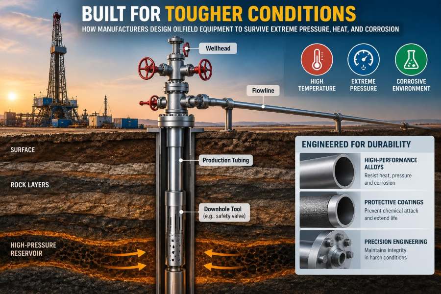

A valve on a wellhead may look like a heavy block of steel, but it can be holding back fluids at pressures that would instantly overwhelm ordinary industrial piping. A drill collar several kilometres below the rig floor may be rotating in hot, abrasive drilling fluid while bending thousands of times. A subsea connector may have to work after years in cold seawater, under immense external pressure, with no technician nearby.
These components do not survive by being merely “strong.” They survive because manufacturers make a long chain of engineering decisions about material chemistry, geometry, heat treatment, seals, surface condition, inspection, and traceability.
That chain matters to everyone in petroleum engineering. Equipment limits affect well design, drilling parameters, production rates, intervention plans, maintenance intervals, and, most importantly, the margins available to manage loss of containment.
Understanding how oilfield equipment is built also makes specifications easier to read. A pressure rating, material class, test requirement, or coating callout is not paperwork around the real equipment. It is part of the equipment’s ability to perform in a specific well environment.
🧭 The operating environment sets the design challenge
Oilfield equipment is designed for a defined service envelope: the credible combinations of pressure, temperature, fluids, loads, and exposure time it may see. A component suitable for a sweet, moderate-temperature land well may be unsuitable for a high-pressure, high-temperature sour-gas well or a deepwater tree.
Manufacturers begin by converting the field problem into design inputs. These include maximum and minimum pressure, temperature cycling, fluid composition, sand production risk, external seawater exposure, expected operating life, and required inspection access.
💥 Pressure is more than a single number
Internal pressure creates hoop stress in cylindrical bodies such as tubing, valves, and pressure vessels. In simple terms, pressure tries to split a cylinder open around its circumference. Larger diameters generally need more wall thickness for the same pressure and material strength.
But equipment rarely sees a perfectly steady load. Pressure surges during valve closure, pump transients, shut-in, gas expansion, or testing can be more damaging than normal operation. Designers consider these transient cases as well as the stated working pressure.
External pressure matters too. Subsea housings, control pods, and instrument enclosures can be compressed by seawater, creating a collapse or buckling problem rather than an internal-burst problem.
🌡️ Heat changes the behavior of metal and seals
Temperature affects nearly every material property that matters. Metals can lose strength at elevated temperature; elastomer seals can soften, swell, harden, or chemically degrade; lubricants can thin; and dissimilar materials expand at different rates.
A pressure-containing joint that seals well at room temperature may leak after repeated heating and cooling. This is why qualification testing often includes thermal cycling rather than a single pressure test at ambient conditions.
At the other extreme, low temperatures can reduce the toughness of some steels. Toughness is the ability to absorb energy before fracturing, and it becomes critical when a flaw, sharp notch, or impact load is present.
🧪 Corrosion begins with the produced-fluid chemistry
“Corrosion resistant” is not a universal description. The right material depends on what is in the fluid, how much water is present, the pressure and temperature, flow conditions, and whether deposits or stagnant zones can form.
Carbon dioxide can dissolve in water and promote so-called sweet corrosion. Hydrogen sulfide creates sour-service concerns, including forms of cracking that can occur when susceptible materials are stressed in a wet H₂S environment. Chlorides in produced water or seawater can intensify localized attack on some alloys.
Manufacturers and operators therefore need a realistic fluid description, not just a statement that the service is “corrosive.”
🧱 Material selection is an engineered trade-off
Carbon and low-alloy steels remain widely used because they are strong, available, machinable, and relatively economical. Where the environment allows their use, they can provide dependable service with corrosion allowance, inhibitors, coatings, or controlled operating conditions.
More severe wells may require stainless steels, nickel-based alloys, duplex stainless steels, or other corrosion-resistant alloys. These choices can resist particular damage mechanisms better, but they also bring higher cost, more demanding machining, welding constraints, and different risks in the wrong environment.
| Material family | Typical advantage | Key limitation to evaluate |
|---|---|---|
| Carbon or low-alloy steel | Strength, availability, practical fabrication | General corrosion and sour-service suitability |
| Stainless steel | Useful corrosion resistance in selected fluids | Localized corrosion and chloride sensitivity vary by grade |
| Duplex stainless steel | High strength with good resistance in many chloride services | Heat input and phase balance require careful control |
| Nickel-based alloy | Strong resistance in demanding sour and hot environments | Cost, lead time, and fabrication complexity |
🧬 Alloy chemistry must be tightly controlled
The name of an alloy is only the start. Manufacturers control chemistry within specified ranges because small changes in elements such as carbon, chromium, nickel, molybdenum, and sulfur can change hardenability, weldability, strength, or corrosion performance.
For sour service, excessive hardness can increase susceptibility to certain cracking mechanisms. For corrosion-resistant alloys, improper composition or undesirable phases can reduce the corrosion margin that justified the material choice.
Certified material test reports connect a heat of steel or alloy to its measured chemistry and mechanical properties. This documentation is meaningful only when physical identification is maintained through every manufacturing step.
🏭 Forging creates a stronger starting shape
Many critical pressure-containing bodies begin as forgings rather than being cut from plate or assembled from multiple pieces. In forging, compressive deformation shapes heated metal and can refine its internal structure while aligning grain flow with the part geometry.
A forged valve body or connector also avoids some welds that would otherwise require their own qualification and inspection. That does not make forging automatically superior in every application, but it is often preferred for highly loaded, pressure-retaining components.
Forging quality still depends on billet cleanliness, heating practice, deformation amount, die design, and subsequent heat treatment. A poor forging process can preserve or create defects rather than eliminate them.
⚙️ Machining turns stock into pressure hardware
Computer-controlled machining creates bores, seal pockets, threads, flange faces, and valve cavities to very tight geometric tolerances. Dimensions matter because small deviations can change thread engagement, seal squeeze, load distribution, or the alignment of moving parts.
Machining also affects surface integrity. Tool marks, chatter, torn metal, or sharp transitions can become stress concentrators or leak paths. A polished-looking surface is not always required, but surfaces that interact with seals, fatigue loads, or corrosive fluids need the finish specified for that function.
📐 Geometry reduces stress concentration
Failure often starts where the local stress is far above the average stress calculated from pressure alone. Threads, cross-bores, abrupt wall-thickness changes, keyways, and sharp internal corners are common locations for stress concentration.
Designers use smooth radii, gradual transitions, suitable thread forms, and sufficient engagement length to reduce these peaks. Finite element analysis can reveal where complex geometry concentrates stress, but its results are only as credible as the loading assumptions, material model, and boundary conditions.
A useful mental model is a paper strip with a notch: it tears at the notch, not in the broad middle. Steel components behave more subtly, but the underlying principle is similar.
🔥 Heat treatment builds the required property balance
Heat treatment changes the microstructure of steel and many alloys. Processes such as quenching and tempering can develop strength while retaining enough toughness for the intended service. Solution treatment and aging may be used for certain corrosion-resistant or high-strength alloys.
The target is a balance, not maximum hardness. Very high hardness may improve wear resistance but can reduce toughness, complicate machining, and create sour-service concerns. Manufacturers verify the resulting properties with representative test samples and hardness checks.
Time, temperature, cooling rate, and section thickness all matter. A thick body may cool differently at its center than near its surface, so process qualification must reflect the actual product size.
🧷 Welding requires its own engineering plan
Some equipment requires weld overlays, attachments, cladding, repair welding, or fabricated structures. Welding locally heats and then cools the material, creating a heat-affected zone whose properties may differ from the parent metal.
A qualified welding procedure defines variables such as filler metal, preheat, heat input, shielding, interpass temperature, and post-weld heat treatment where needed. The procedure is demonstrated through testing before being used on production hardware.
Uncontrolled repair welding is particularly risky. It can leave residual stress, unacceptable hardness, lack of fusion, or metallurgy inconsistent with the original qualification.
🛡️ Cladding and overlays protect the wetted surface
In some high-pressure equipment, using a solid corrosion-resistant alloy for the entire body would be expensive and unnecessary. A common alternative is a strong carbon- or low-alloy-steel body with a corrosion-resistant weld overlay or metallurgically bonded cladding on fluid-exposed surfaces.
This approach can be effective, but it creates interfaces that must be controlled. The overlay needs adequate thickness after machining, sound bonding, compatible chemistry, and coverage in every area exposed to the process fluid.
It is not a shortcut around materials engineering. It is a different materials system with its own inspection and qualification needs.
⭕ Seals are often the true limiting component
A pressure boundary is only as reliable as its seals. Metal-to-metal seals, elastomeric seals, thermoplastic elements, and graphite-based packing each serve different temperature, pressure, chemical, and motion conditions.
Elastomers may absorb hydrocarbons, react with chemicals, extrude into clearance gaps, or suffer rapid gas decompression when high-pressure gas escapes from the material too quickly. Metal seals tolerate harsher temperatures but demand highly controlled geometry and surface finish.
Seal selection must account for installation damage, debris, extrusion gap, pressure direction, cycling, and compatibility with control fluids as well as produced fluids.
🔩 Threads and connectors carry hidden complexity
Threaded connections do more than join two parts. They transmit axial load, may contain pressure, often provide a metal seal, and must survive repeated make-up and break-out in some applications.
Connection performance depends on thread profile, taper, shoulder geometry, lubricant, make-up torque, cleanliness, and dimensional control. Galling, a severe form of adhesive wear between sliding metal surfaces, can damage threads or sealing faces during assembly.
Field crews need the manufacturer’s handling and torque procedures. A high-quality connection can be compromised by incorrect compound, damaged protectors, or an improperly calibrated torque system.
🌊 Subsea service adds external pressure and access limits
Subsea equipment faces a different maintenance reality: recovery can be difficult, costly, and weather-dependent. Manufacturers therefore design for long unattended service, corrosion from seawater, hydraulic-fluid compatibility, marine growth considerations, and external hydrostatic pressure.
Pressure compensation systems may balance internal fluid pressure with seawater pressure to reduce differential loading on housings and seals. Electrical penetrators and hydraulic connectors must also keep seawater out while maintaining signal or fluid integrity.
Redundancy can improve availability, but it also adds components and interfaces. The best arrangement depends on which failure modes are most consequential and how the system can be tested or isolated.
🏜️ Sand, erosion, and flow velocity wear equipment away
Corrosion is not the only fluid-driven damage mechanism. Produced sand, drilling cuttings, and high-velocity multiphase flow can erode chokes, bends, valve trims, and restriction points. Erosion accelerates when particles strike a surface at damaging angles and velocities.
Hard-facing materials, erosion-resistant trims, smoother flow paths, and controlled operating envelopes can reduce the problem. However, a harder surface is not automatically better if it becomes brittle, cracks under impact, or is incompatible with the base metal.
Manufacturers may use flow analysis and laboratory erosion tests, but field performance still depends on actual sand rate, particle size, fluid regime, and operating transients.
🧫 Sour service demands disciplined hardness control
Wet hydrogen sulfide service is a classic example of why material selection cannot rely on yield strength alone. Under certain conditions, susceptible steels can experience hydrogen-related cracking or other environmentally assisted damage, especially where tensile stress and high hardness are present.
Specifications for sour service commonly restrict material hardness and require controlled chemistry, heat treatment, and testing. The applicable requirements depend on the equipment type and service conditions; they should be selected through the project’s governing material specification rather than copied casually from another job.
Residual stresses from machining, forming, or welding deserve attention because they can contribute to the total stress state at vulnerable locations.
🔍 Non-destructive testing looks below the surface
Non-destructive testing, or NDT, checks for defects without sacrificing the component. Different methods see different kinds of discontinuities, so no single method answers every question.
- Ultrasonic testing uses sound waves to detect internal flaws or measure thickness.
- Magnetic particle testing can reveal surface and near-surface indications in ferromagnetic materials.
- Liquid penetrant testing highlights surface-breaking flaws on suitable clean surfaces.
- Radiographic testing uses radiation to examine internal features, often in welds.
An indication is not automatically a rejectable defect. Acceptance depends on its size, location, orientation, component function, and the governing acceptance criteria.
📏 Dimensional inspection verifies fit and function
Pressure tests cannot confirm every dimensional requirement. Coordinate measuring systems, gauges, thread inspection tools, and profile measurement verify features that determine assembly and sealing performance.
Critical dimensions often include bore size, wall thickness, flange geometry, thread lead, seal-groove depth, surface roughness, and concentricity. Measuring these after all relevant heat treatment, coating, and finishing steps prevents an earlier result from being mistaken for the final condition.
Inspection plans should focus effort where a deviation has the greatest consequence, rather than treating every dimension as equally critical.
💧 Pressure testing proves boundary integrity
Hydrostatic testing uses liquid, usually water, to apply pressure and verify that a pressure boundary does not leak or rupture under the prescribed test conditions. Because liquids store less compressible energy than gases, hydrostatic tests are generally preferred where practical.
Pneumatic testing can be necessary in certain situations, but compressed gas stores substantial energy and therefore requires more stringent hazard controls. Test pressure, hold time, temperature, allowable leakage, instrumentation, barriers, and personnel exclusion zones should follow the approved procedure.
A passed pressure test is powerful evidence, but it does not prove unlimited fatigue life, corrosion resistance, or suitability for a fluid not considered in the design.
🔄 Fatigue testing addresses repeated loading
Equipment can fail below its static strength when it experiences enough load cycles. This is fatigue. Pressure fluctuations, rotating bending, vibration, valve cycling, and thermal expansion can all initiate fatigue cracks, often at stress concentrators.
Manufacturers may qualify components with cyclic pressure testing, bending tests, torque cycling, or functional cycling. The test sequence should represent the dominant field loads rather than merely repeating the easiest load to apply in a laboratory.
Operational data also matters. A component designed for infrequent shut-ins may accumulate very different damage if used in aggressive control service.
🧾 Traceability follows the component from melt to shipment
Traceability connects the finished serial number to material certificates, forging records, heat-treatment charts, welding records, inspection results, pressure tests, and approved deviations. It allows a manufacturer and operator to understand exactly what was built.
Physical marking must survive processing without creating harmful notches or confusion. When components are cut into smaller pieces, identification control becomes especially important; mixing similar-looking materials can have serious consequences.
Good traceability is also a learning tool. If a field issue occurs, records help determine whether it relates to material, process, assembly, operating conditions, or a combination.
✅ Quality plans make verification intentional
A quality plan identifies the checks required during manufacturing, who performs them, what records are produced, and which stages require customer or independent witness. It turns broad requirements into a controlled sequence of hold points and acceptance decisions.
Useful plans are risk-based. A safety-critical forged body may warrant extensive material and volumetric examination, while a non-pressure external bracket may need simpler verification. More paperwork is not automatically better; the goal is evidence targeted to credible failure modes.
When a nonconformance appears, it should be evaluated against design intent. Simply blending, welding, or accepting a deviation for schedule reasons can undermine a carefully built qualification basis.
📚 Standards create a common technical language
Oilfield equipment is often designed and manufactured to recognized industry standards, project specifications, and customer requirements. These documents provide common definitions for ratings, materials, testing, documentation, and product-specific performance expectations.
However, a standard does not replace engineering judgment. Its scope may not cover every unusual fluid, load case, installation method, or combined environmental effect. The purchaser still needs to specify the actual service conditions, and the manufacturer must identify any assumptions or limitations.
Using an outdated requirement, combining clauses from incompatible editions, or assuming that a product certification applies to a modified configuration are common specification traps.
🚚 Packaging and handling can undo careful manufacturing
After final inspection, equipment still needs protection from impact, moisture, contamination, and damage to precision sealing surfaces. Thread protectors, flange covers, desiccants, lifting points, and clear preservation instructions are functional controls, not cosmetic extras.
Incorrect lifting can bend slender tools, damage coatings, or impose unintended loads on connectors. Storage can also matter: trapped water, damaged packaging, ultraviolet exposure, or incompatible preservation compounds may degrade a component before installation.
The receiving inspection should confirm identity, preservation, visible condition, documentation, and any required shelf-life controls for seals or chemicals.
🧰 Field assembly is part of the equipment system
The manufacturer controls the product leaving the factory, but field assembly determines the final installed condition. Cleanliness, alignment, correct fasteners, calibrated torque tools, compatible lubricants, and trained personnel all affect pressure integrity.
Consider a flange with a carefully machined ring-groove seal. If the groove is scratched during handling or the fasteners are unevenly tightened, the hardware may be within its original manufacturing specification yet still leak in service.
Installation instructions should explain the critical controls, not merely list generic safety language. Where assembly is especially sensitive, supervised make-up or field acceptance testing may be justified.
⚠️ Common shortcuts that create long-term risk
Many equipment problems are not caused by one dramatic mistake. They emerge from small compromises that align: a material substitution without full review, an undocumented repair, skipped surface preparation, reused damaged seal, incomplete test record, or service change that was never communicated.
- Choosing material by strength alone rather than fluid compatibility.
- Assuming a successful hydrotest validates corrosion and fatigue performance.
- Allowing hardness or weld repairs outside the qualified process.
- Using generic installation torque where a connection-specific procedure is required.
- Treating missing traceability as an administrative issue rather than a technical gap.
The corrective action is not simply more inspection. It is better control of requirements, process discipline, and feedback from field performance.
🤝 Manufacturer and operator responsibilities must meet
Reliable equipment depends on a clear exchange of information. The operator or purchaser provides the service definition, design life, fluid data, operating scenarios, and applicable requirements. The manufacturer translates those inputs into a qualified design and discloses operating limits, maintenance needs, and assumptions.
Ambiguity creates risk at the interfaces. For example, “sour capable” is not a complete service description, and “high temperature” does not tell a seal designer how long the component will remain hot, what fluid it sees, or how rapidly it cycles.
Early technical review is usually more effective than discovering conflicts after material has been purchased or equipment has reached the location.
🧠 Digital tools improve consistency, not engineering judgment
Modern manufacturing increasingly uses digital design models, machining data, process monitoring, electronic inspection records, and serial-number databases. These tools can reduce transcription errors, improve repeatability, and make records easier to retrieve.
They do not eliminate the need for competent review. A measurement system can record a value accurately while the wrong acceptance criterion is applied; a simulation can calculate a precise answer to an unrealistic load case.
The strongest systems combine reliable data capture with experienced people who understand material behavior, process capability, and field consequences.
🧩 The core principle: engineer the whole pressure boundary
No isolated feature makes oilfield equipment reliable. A high-grade alloy cannot compensate for an incompatible seal. A flawless forging cannot overcome poor thread make-up. A passed factory test cannot erase a service environment that was incorrectly specified.
The core principle is to treat equipment as a connected system: service conditions define the hazards; design and materials resist them; controlled manufacturing produces the intended properties; inspection verifies critical features; and correct installation preserves the result.
For students, this is a useful way to read a datasheet or drawing. For working professionals, it is a reminder to ask where the assumptions came from, what damage mechanism governs, and whether every handoff protects the original design intent.
Oilfield equipment survives extreme service when every decision—from fluid specification to final make-up—supports the same engineered barrier against pressure, heat, wear, and corrosion. 🛢️⚙️🔍