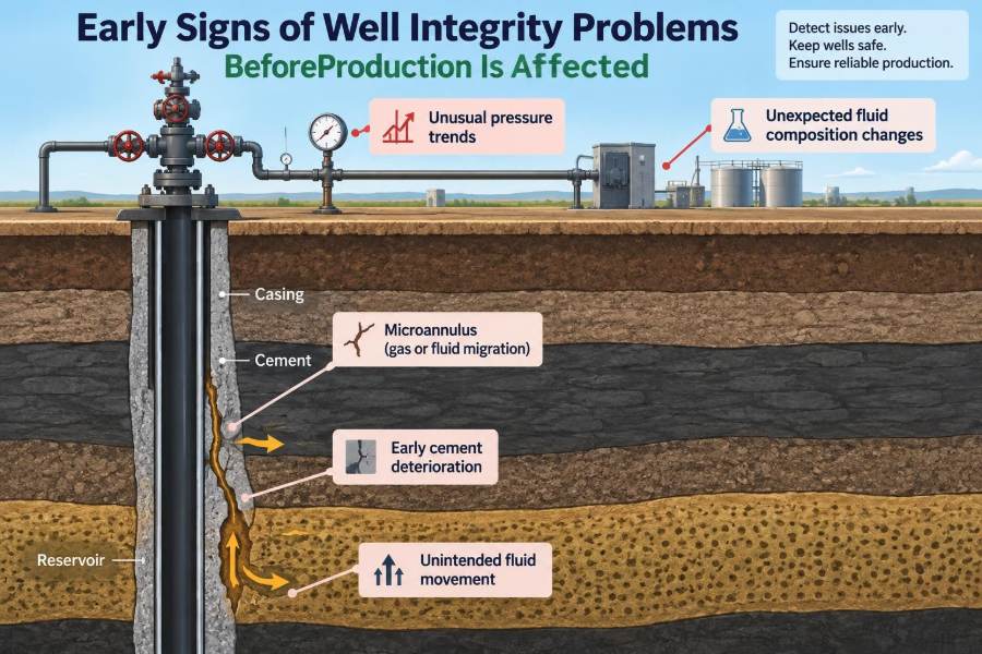

A well can continue meeting its production target while its barriers are beginning to weaken. The separator sees steady rates, the water cut appears familiar, and routine reports contain no obvious alarm. Yet a small pressure anomaly, a change in annulus behavior, or an unexpected gas reading may already be signaling a developing integrity issue.
This is what makes well integrity management difficult: production is a late indicator for many failure mechanisms. By the time rates fall or unwanted fluids reach the surface, the pathway behind the problem may be more established, more costly to diagnose, and harder to repair.
For students, the topic connects drilling, completions, production, reservoir engineering, and process safety. For operating teams, it is a practical discipline of recognizing weak signals, checking their meaning, and acting before a loss of containment becomes a production or safety event.
The objective is not to treat every unusual reading as proof of failure. It is to understand what normal behavior looks like, investigate meaningful deviations, and preserve the barriers that keep formation fluids in their intended flow path.
🧱 What Well Integrity Means in Practice
Well integrity is the ability of a well to contain fluids and pressures and to control their movement throughout its life. A sound well directs produced fluids from the reservoir to the surface through designed flow paths while preventing unintended communication between formations, annuli, and the environment.
Integrity is not a single piece of equipment. It depends on a barrier system that can include cement, casing, tubing, packers, wellhead seals, valves, plugs, and operating procedures. The system is only as reliable as its barriers and the way they are monitored.
🛡️ Barriers Work as a System
Primary and secondary barriers provide independent layers of protection. In a producing well, tubing and a production packer may form the primary containment path, while casing, cement, and wellhead equipment contribute to secondary containment.
A barrier need not visibly fail for risk to increase. Corrosion thinning, elastomer aging, cement microannuli, or a valve that does not fully seal can reduce barrier performance gradually. Multiple modest weaknesses can become significant when pressure, temperature, or operating conditions change.
📉 Why Production Can Remain Normal
Reservoir deliverability can mask an early leak. A small tubing leak, for example, may not immediately reduce surface oil rate if the reservoir has enough energy to sustain flow. Instead, some produced fluid may enter the tubing-casing annulus, creating an abnormal pressure response before rate losses are visible.
Likewise, a narrow channel behind casing may permit low-volume gas migration without changing the main production stream. Stable production should therefore be interpreted as evidence that the well is producing—not as proof that every barrier is healthy.
📍 Establishing the Well’s Normal Fingerprint
Early detection starts with a credible baseline. Teams need to know how tubing pressure, casing pressure, annulus pressure, temperature, fluid composition, injection rate, and shut-in behavior normally respond for that particular well.
A baseline is not simply one reading taken after startup. It is a history collected across normal operating states: flowing, shut in, restarting, unloading, and changing choke conditions. Without that context, an unusual value can be mistaken for normal variability—or routine behavior can be mistaken for a leak.
📈 Sustained Annulus Pressure
Sustained casing pressure is pressure that rebuilds after being bled down, often under controlled monitoring conditions. It is one of the most recognized indicators requiring investigation because it may reflect fluid migration, trapped thermal pressure, communication with a pressure source, or a leaking barrier.
It does not automatically identify the failure mechanism. An annulus can be pressured by thermal expansion of trapped liquid, for example, particularly after temperature changes. The key question is whether the pressure behavior matches the well design, fluid inventory, and operating history.
🔄 Pressure Rebuild Patterns Tell a Story
The shape of a pressure trend often contains more information than a single maximum reading. Fast rebuild after bleed-down may suggest a relatively open communication path, while slow rebuilding may be consistent with restricted influx, gas migration, or a large trapped volume responding to temperature.
Engineers should document the initial pressure, bleed-down volume, fluid released, shut-in duration, temperature conditions, and rebuild profile. Comparing like-for-like tests is essential; a short observation window cannot safely be compared with a long one without context.
🌡️ Separating Thermal Pressure From Influx
Trapped liquids expand when heated and contract when cooled. In annuli that are sealed or poorly vented, temperature changes during production, shut-in, stimulation, or nearby operations can create pressure changes even when no external fluid is entering.
Thermal pressure commonly follows temperature or operating cycles and may decline as the system cools. Influx-driven pressure can behave differently, but field behavior is rarely so simple that it can be diagnosed from one trend alone. Fluid sampling, volume tracking, and engineering review help distinguish the possibilities.
💨 Unexpected Gas at the Surface
Gas detected at an annulus vent, wellhead connection, cellar, or other monitored location deserves prompt, controlled assessment. The gas may originate from the producing interval, a shallower gas-bearing zone, residual gas from prior operations, or another source.
Safe gas monitoring is not merely a production task. It supports both personnel protection and diagnosis. The location, rate, composition where sampling is appropriate, pressure correlation, and response to shut-in conditions can help determine whether the observation indicates a barrier concern.
🧪 Changes in Annulus Fluid
An annulus that was expected to contain clean completion brine but begins returning oil, gas-cut liquid, solids, or water with altered salinity has changed condition. That change may indicate communication with produced fluids, formation water, a workover fluid, or material left from an earlier operation.
Fluid appearance alone is not definitive. Sampling should follow site safety and contamination-control practices, and results should be compared with known production and completion fluids. The valuable clue is often the change from the annulus’s established inventory.
🧂 Water Chemistry Can Be a Clue
Water chemistry can help distinguish fluids that look similar at the surface. Parameters such as salinity, ion content, pH, solids, oil content, or scale-forming tendency may indicate whether sampled water resembles packer fluid, produced water, injected water, or a shallower formation source.
Interpretation requires care. Mixing, treatment chemicals, sampling contamination, and changing reservoir water chemistry can obscure the signal. Chemistry is strongest when used with pressure data, completion records, and a defined sampling chain of custody.
🎧 Audible Leaks and Localized Venting
A hiss at a wellhead connection, unusual venting, bubbles in a monitored water-filled area, or recurring odor reports may be early field observations rather than conclusive diagnoses. They should not be ignored simply because production remains steady.
Personnel should not attempt to locate a suspected leak by approaching a potentially hazardous release. Follow site procedures for exclusion zones, gas detection, notification, and isolation. A visible or audible symptom is a reason to secure the area and gather evidence safely.
🔩 Wellhead Seal and Valve Warning Signs
Wellhead seals and valves operate under pressure, temperature cycling, vibration, and environmental exposure. External seepage, corrosion around seal areas, recurring valve passing, damaged threads, or difficulty holding a pressure test can indicate declining equipment condition.
Not every wet surface is a pressure leak; condensation, wash water, and residual lubricants can mislead inspections. Still, recurring evidence at the same location should trigger verification rather than repeated cleanup without investigation.
🧯 Corrosion Is Often Quiet at First
Internal corrosion can thin tubing or casing with little immediate production impact. It may be driven by water, carbon dioxide, hydrogen sulfide, oxygen contamination, bacteria, solids erosion, incompatible chemicals, or ineffective inhibitor delivery.
Early clues include increasing iron content in produced water, corrosion products in filters, changes in chemical usage, localized metal loss found during inspection, or unexplained pressure communication. None of these independently proves a tubing leak, but together they can justify targeted evaluation.
🧱 Cement and Microannulus Concerns
Cement is intended to support casing and provide zonal isolation. A microannulus is a very small gap at the casing-cement interface or within the cement system that can develop because of shrinkage, debonding, stress changes, or incomplete bonding.
Such pathways may allow gas or fluid movement behind casing without immediate production changes. Diagnosing cement-related communication can be difficult because the behavior depends on formation pressures, permeability, cement quality, and the geometry of the pathway.
🧭 Crossflow Between Formations
Unintended crossflow occurs when fluid moves from one subsurface zone to another through a compromised wellbore pathway. This can affect water disposal, injection conformance, groundwater protection, reservoir management, and later abandonment obligations.
A production well may show subtle signs such as unexplained annulus behavior or fluid composition changes. An injection well may show pressure-rate behavior inconsistent with its expected injectivity. The well’s construction and the pressure relationship between zones are central to the assessment.
💧 Unexplained Water or Gas Changes
A rising water cut or gas-oil ratio can result from ordinary reservoir processes, changing drawdown, coning, breakthrough, or completion behavior. It can also, in some circumstances, be associated with an integrity issue such as behind-pipe communication or a leaking completion component.
The mistake is to assign every production change to either the reservoir or the wellbore without testing alternatives. Reservoir surveillance and well integrity surveillance should inform each other, especially when the timing of a change coincides with pressure anomalies or intervention activity.
🧰 Tubing Leak Signatures
A tubing leak may permit production into the tubing-casing annulus or allow annulus fluid into the tubing, depending on pressure relationships. Possible signs include unexpected annulus pressure, altered produced-fluid behavior, failure to hold pressure during a tubing test, or mismatched rates between surface measurements.
Consider a hypothetical well where annulus pressure appears only when the well flows and declines after shut-in. That pattern could be consistent with a tubing-related pathway, but it must be tested against packer performance, thermal effects, and the detailed pressure history before drawing conclusions.
🧷 Packer Degradation and Communication
Packers isolate the tubing-casing annulus from producing conditions. Their seals can be affected by differential pressure, temperature cycles, elastomer compatibility, debris, mechanical movement, corrosion, and long service life.
A failed packer and a tubing leak can produce similar surface symptoms, which is why diagnosis should not rely on one test. Completion schematic review, pressure testing, temperature or noise surveys where appropriate, and intervention history help narrow the likely location.
📊 The Value of Trending, Not Snapshots
One pressure reading is a photograph; a trend is a short film. Time-series data reveals whether an anomaly is stable, cycling with operations, gradually worsening, or linked to a particular event such as a choke change, chemical treatment, or shut-in.
Useful trends align data on a common timeline: pressures, temperatures, flow rates, choke position, chemical volumes, venting events, interventions, and alarms. This simple discipline often exposes relationships that isolated spreadsheets hide.
🖥️ Alarm Limits Need Engineering Context
Automated alarms can catch a rapid departure from expected conditions, but alarm settings should be based on the well’s operating envelope and barrier philosophy. A limit that is too broad may normalize a developing problem; one that is too narrow can create nuisance alarms that operators learn to disregard.
Good alarm management distinguishes between an operational advisory, a required verification, and an escalation requiring immediate action. The response should specify who reviews the event, what data to capture, and when operations must be restricted.
🧾 Records Make Diagnosis Possible
Well integrity investigation depends heavily on records: drilling reports, cementing data, casing and tubing tallies, completion diagrams, pressure-test results, workover history, chemical programs, and prior anomaly reports. Missing records do not create a leak, but they make safe decisions slower and less certain.
Maintain a current barrier schematic that reflects the well as it exists today, not only as it was originally designed. Each intervention can alter equipment position, fluid inventory, pressure exposure, and the credibility of earlier assumptions.
🔍 Diagnostic Tools Have Different Jobs
No single diagnostic tool answers every integrity question. The selection should be driven by the suspected pathway, well accessibility, pressure conditions, completion design, and the decision that the result must support.
| Tool or method | What it can help identify | Key limitation |
|---|---|---|
| Pressure testing | Whether a defined component or volume holds pressure | May not locate the leak path |
| Temperature survey | Fluid movement or thermal anomalies behind pipe | Interpretation can be affected by operating conditions |
| Noise logging | Active fluid or gas movement at a point in time | Small or intermittent flows may be difficult to detect |
| Mechanical integrity test | Integrity of a specified well system under a procedure | Scope depends on test design and accessible barriers |
| Fluid sampling | Likely origin or mixing of fluids | Requires representative, safely obtained samples |
Tool results should be integrated rather than treated as verdicts in isolation. A negative survey can be useful evidence, but it may not eliminate a pathway that was inactive during the logging run.
🧪 Pressure Testing Requires Discipline
A pressure test is meaningful only when the test boundary is understood. Teams should define what volume is being tested, which valves are included, the test medium, target pressure, stabilization period, temperature effects, acceptance criteria, and contingency actions.
Common errors include testing through a passing valve, assuming gauge accuracy without verification, ignoring trapped pressure, or comparing results from different configurations. Clear isolation and contemporaneous notes are as valuable as the final pressure chart.
🚨 When an Anomaly Requires Immediate Escalation
Some observations warrant urgent action before a complete diagnosis is available. These include an uncontrolled release, confirmed hazardous gas, rapidly increasing pressure beyond the approved operating envelope, a failed barrier during a critical operation, or evidence that fluids may be reaching an unintended zone or the environment.
Site-specific procedures govern the response, but the priorities are consistent: protect people, control the source where it is safe to do so, monitor conditions, notify responsible personnel, and preserve accurate information for the investigation. Production continuity must not override barrier safety.
🧑🔧 Field Observations Matter
Operators and technicians are often the first people to notice a valve that behaves differently, a pressure that rebuilds faster than usual, an odd odor, or a recurring trace of fluid. These observations are valuable when they are recorded with time, operating condition, location, and supporting measurements.
A healthy reporting culture avoids both extremes: dismissing observations as routine and declaring a major failure without evidence. The practical standard is to report the deviation, make the situation safe, and allow the appropriate technical review to determine significance.
🤝 Integrity Is a Cross-Discipline Task
Production personnel understand daily operating behavior. Completion engineers understand downhole hardware. Reservoir engineers assess formation-driven changes. Corrosion specialists evaluate degradation mechanisms, while HSE and regulatory teams focus on containment and response obligations.
These perspectives are strongest when combined early. A pressure anomaly may look operational to one team and geological to another; a joint review can prevent a narrow interpretation from delaying the correct investigation.
📝 A Practical Response Workflow
A consistent workflow prevents weak signals from disappearing into daily operations. It also makes sure minor anomalies are handled proportionately rather than with either neglect or unnecessary intervention.
- Verify the observation: check gauges, valve positions, calibration status, and operating conditions.
- Make the area safe: apply gas monitoring, exclusion, isolation, or shutdown measures as required.
- Compare with the baseline: review prior trends, fluid inventories, and similar operating states.
- Define credible mechanisms: include thermal effects, trapped pressure, tubing or packer issues, valve passing, and behind-pipe communication.
- Select proportionate diagnostics: choose tests that can distinguish among the leading explanations.
- Document and reassess: update the barrier status and escalate if risk or uncertainty remains unacceptable.
⚠️ Common Mistakes That Delay Detection
One common mistake is treating a pressure bleed-down as a solution rather than a diagnostic event. If the pressure returns, its rebuild behavior and released fluid are evidence that should be captured, not discarded.
Other avoidable errors include relying on a single gauge, failing to record operating conditions, assuming all annulus pressure is thermal, and postponing review because production is unaffected. The opposite error—ordering every possible log without a clear diagnostic question—can also waste time and create unnecessary exposure.
🔧 Prevention Begins Before the Well Produces
Early-warning capability is designed into a well long before the first production test. Quality assurance during drilling and cementing, appropriate material selection, verified pressure-control equipment, compatible completion fluids, and accessible monitoring points all influence future integrity management.
During operations, prevention includes corrosion control, chemical-program verification, disciplined pressure testing, planned inspection, and careful management of pressure and temperature cycles. Preventive work does not eliminate degradation, but it improves the likelihood that degradation is detected while options remain available.
🎯 The Core Principle: Detect Change Before Consequence
The earliest signs of well integrity problems are often not dramatic. They are deviations: an annulus pressure that rebuilds differently, a fluid sample that no longer matches expectations, a valve that starts passing, or a trend that no longer fits the well’s normal fingerprint.
Good integrity management turns those deviations into structured questions. What barrier could be affected? What other explanations are plausible? What evidence would distinguish them? And what operating restrictions are appropriate until the answer is clear?
The most effective well integrity program does not wait for lost production to announce a problem; it watches for changing barrier behavior and responds before that change becomes a consequence. 🛢️🛡️📈