
A producing well can look healthy on a daily report while quietly losing its ability to flow. The tubing pressure rises, liquid rate falls, gas-liquid behavior becomes less stable, and a well that once flowed naturally needs more and more help from the reservoir just to lift fluids to surface.
That moment creates a familiar field question: should the team intervene now, or allow the well to continue flowing until rates decline further? Installing artificial lift too early can add cost and operating complexity. Waiting too long can leave recoverable production in the wellbore and may make restart more difficult.
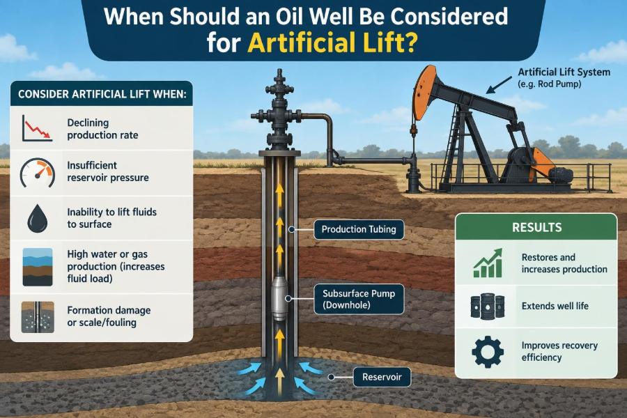
Artificial lift is not simply a response to “low production.” It is a deliberate way to reduce the flowing bottomhole pressure or provide energy to the produced fluids when the reservoir can no longer move them to surface at an economic rate on its own.
The best decision comes from understanding the complete production system: reservoir, completion, tubing, fluids, surface backpressure, operating constraints, and economics. This article explains the signs, calculations, and practical trade-offs behind that decision.
🛢️ Start With the Meaning of Artificial Lift
Artificial lift is any method that adds energy to a well’s produced fluids or reduces the pressure opposing inflow from the reservoir. Its purpose is to maintain or increase liquid production when natural reservoir energy is insufficient for the desired operating condition.
Common systems include sucker-rod pumping, electrical submersible pumps (ESPs), gas lift, progressing cavity pumps (PCPs), hydraulic pumping, and plunger lift. They do not create hydrocarbons or improve reservoir permeability by themselves. They help the well deliver fluids that the reservoir is already capable of supplying at a lower flowing pressure.
🌊 Natural Flow Is a Balance, Not a Permanent State
A naturally flowing well works when reservoir pressure and gas expansion can overcome all pressure losses between the reservoir and the separator. Those losses include flow through the formation, perforations, tubing, wellhead equipment, flowline, choke, and surface facilities.
As a reservoir depletes, its pressure commonly declines. Water production may increase, gas behavior may change, and the fluid column inside the tubing may become heavier. Eventually, the available pressure is no longer enough to sustain a useful surface rate.
The well may still contain movable oil and water. It simply cannot lift that fluid efficiently under the existing flowing conditions.
📉 The First Warning: Declining Production Rate
A declining oil or liquid rate is often the first visible signal, but it is not enough on its own to justify artificial lift. Production decline can result from reservoir depletion, scale, wax, sand, changing choke settings, facility constraints, liquid loading, or mechanical restrictions.
The useful question is: is the rate declining because the well needs lower flowing bottomhole pressure, or because something else is restricting production? A pump will not solve a plugged perforation interval, a closed valve, or a constrained separator.
Trend data is more valuable than a single test. Compare liquid rate, oil cut, gas-oil ratio, tubing-head pressure, casing pressure, water cut, choke size, and downtime over a meaningful period.
🧭 Understand Inflow Performance Before Choosing Lift
The inflow performance relationship, usually called IPR, describes how much fluid the reservoir can deliver at different flowing bottomhole pressures. In simple terms, lower bottomhole pressure generally allows greater drawdown and greater inflow—up to the limits set by reservoir and completion behavior.
An IPR can be developed from pressure-transient information, production tests, fluid properties, reservoir data, or calibrated models. Its reliability depends on the quality of the inputs. A calculated IPR should be treated as a decision tool, not an unquestionable description of the reservoir.
If reducing flowing bottomhole pressure is predicted to create meaningful additional inflow, artificial lift may have a strong technical case. If inflow remains poor even at low pressure, the well may need a reservoir or completion diagnosis first.
📈 Read the Outflow Side of the System
Outflow performance describes the pressure required to move fluids from the sandface to the separator at a chosen rate. It includes hydrostatic pressure from the fluid column, friction in tubing and flowlines, acceleration effects, and surface backpressure.
Production engineers often visualize the operating point where the IPR and vertical lift performance, or VLP, curves intersect. That intersection is the rate the well can sustain for a specified set of conditions.
Artificial lift changes the outflow requirement. A pump can reduce the effective hydrostatic burden; gas lift can lighten the fluid column. The new operating point may move to a higher production rate if the reservoir can respond.
🔁 A Nodal Analysis Shows Whether Lift Has a Job to Do
Nodal analysis connects inflow and outflow models at selected points in the production system. It helps distinguish a reservoir-limited well from a wellbore- or surface-limited well.
For example, a hypothetical well may have adequate reservoir deliverability, but high fluid density and long tubing create a large hydrostatic pressure loss. Modeling may show that reducing the fluid-column pressure produces substantial extra liquid. That is a classic artificial-lift opportunity.
Conversely, if the modeled inflow is weak at every reasonable bottomhole pressure, installing a larger pump may mostly increase drawdown, gas interference, or water production without delivering a durable oil-rate gain.
⚖️ The Economic Limit Is Different From the Physical Limit
A well can be physically capable of flowing while no longer being economically attractive without lift. It can also require lift technically but fail to justify the capital, power, maintenance, and intervention expense.
The relevant comparison is incremental value versus incremental cost. Estimate the expected production response, production decline, fluid handling cost, energy use, chemical needs, workover exposure, equipment life, and likely downtime.
Economic analysis should also include the value of preserving production continuity. A delayed lift installation may lead to unstable flow, repeated shutdowns, or loss of operational flexibility even before the well reaches a strict economic limit.
🧪 Fluid Properties Change the Timing
Oil viscosity, API gravity, water cut, gas fraction, emulsion tendency, solids content, and temperature all affect lifting behavior. A light, low-viscosity oil may continue to flow naturally at conditions where a viscous crude would require mechanical assistance.
As water cut rises, the produced liquid column may become denser or simply larger in volume. Higher water production can increase the power required for pumping and raise disposal or treatment costs, even if gross liquid rate increases.
Fluid samples and representative PVT data matter. Designing from assumed properties can lead to a pump or gas-lift system that operates far from its intended range.
💨 Gas Can Help the Well—Until It Does Not
Produced gas can support natural flow by expanding and reducing average fluid density. In some wells, however, declining pressure changes gas liberation and flow regime in ways that make production erratic.
Free gas entering a downhole pump can reduce pump efficiency, cause gas locking, increase vibration, and complicate sizing. In gas lift, gas is intentionally injected, but injection depth, gas availability, valve behavior, and unloading performance still determine whether the system works as planned.
A high gas-oil ratio is therefore not an automatic reason to select one lift method. Engineers need to know where the gas is entering, how it is distributed, and how it behaves at operating pressure.
💧 Rising Water Cut Often Changes the Problem
Many mature wells need artificial lift because they are moving larger liquid volumes with less available reservoir pressure. Water can maintain gross fluid rate while oil rate declines, making a surface rate alone misleading.
Before installing lift, separate the objectives: is the goal to increase oil rate, maintain total liquid rate, control drawdown, delay shut-in, or manage water production? These objectives can point to different settings and sometimes different technologies.
In a water-prone reservoir, aggressive drawdown may accelerate water coning or water cresting. Artificial lift should be coordinated with reservoir surveillance rather than treated as an isolated mechanical upgrade.
🕳️ Well Geometry Sets Practical Limits
Depth, deviation, dogleg severity, casing size, tubing size, completion architecture, and perforation location all influence lift selection. A method that is excellent in a vertical well may be difficult to install, operate, or service in a highly deviated well.
Rod pumps, for example, can face rod wear and friction challenges in deviated trajectories. ESPs require adequate internal diameter and attention to cable deployment. Gas lift depends on valve placement and injection-gas access.
Always begin with a current well schematic. It should show tubular sizes, restrictions, packers, safety valves, perforations, measured depths, true vertical depths, and any known integrity concerns.
🧱 Confirm Completion and Well Integrity First
Artificial lift increases operational demands on the well. A leaking tubing string, failed packer, corroded casing, damaged safety valve, or unreliable wellhead can undermine performance and create safety or environmental risk.
Pressure tests, integrity records, annular-pressure history, corrosion assessment, and recent intervention information should be reviewed before installation. A lift design based on a sound tubing-casing pressure differential may fail if unrecognized communication exists behind pipe.
Addressing integrity first can be more economical than repeatedly troubleshooting a lift system that is compensating for a mechanical failure.
🧹 Rule Out Remediable Restrictions
Not every underperforming well needs artificial lift. Scale, wax, asphaltenes, fines migration, salt deposition, tubing damage, restricted chokes, plugged perforations, and flowline constraints can all reduce production.
A disciplined diagnosis may include pressure surveys, production logging where justified, fluid analysis, well-test review, temperature information, and inspection of surface equipment. The exact program depends on risk, cost, and available evidence.
- Check whether surface backpressure has increased because of a separator, line, or choke constraint.
- Compare current tubing pressure with prior stable operating periods.
- Investigate whether cleanout, chemical treatment, or reperforating could restore flow.
- Verify that measured rates and pressure instruments are credible.
Lift should solve a lifting problem, not conceal a restriction that needs removal.
🔌 Electrical Submersible Pumps Suit High Liquid Volumes
An ESP is a multistage centrifugal pump placed downhole and driven by an electric motor. It is commonly considered where wells require substantial liquid handling and have suitable casing, power supply, and completion conditions.
ESPs can provide large pressure boosts, but they are sensitive to operating outside their preferred flow range, abrasive solids, gas interference, high temperature, scale, and electrical-system problems. Installation and retrieval can require a workover or rigless intervention depending on the completion.
They are often strong candidates in high-rate, relatively deep wells where the production target justifies the equipment and power infrastructure.
🐎 Rod Pumps Fit Many Moderate-Rate Wells
Sucker-rod pumping uses a surface pumping unit, rods, and a downhole reciprocating pump. It is widely used because the surface drive is visible, familiar, and often straightforward to monitor and repair.
Rod pumping can be effective for moderate liquid rates, especially in wells with manageable depth and deviation. It offers flexibility through stroke length, speed, pump size, and control settings.
Its limitations include rod and tubing wear, gas interference, solids-related wear, and practical depth or load constraints. A rod-pump design should consider polished-rod loads, fluid pound, pump fillage, and the complete rod-string stress envelope.
🔥 Gas Lift Offers Flexibility When Injection Gas Exists
Gas lift injects high-pressure gas into the production tubing through valves installed in mandrels. The injected gas reduces the density of the tubing fluid column, lowering the pressure needed to lift fluids to surface.
It can be especially attractive in deviated wells, offshore settings, wells with solids, and fields where a reliable gas-compression and distribution system already exists. It also allows changes in injection rate without pulling the completion.
Its main dependencies are injection-gas availability, compression capacity, gas allocation discipline, valve design, and operating surveillance. A gas-lifted well may underperform because of system-wide gas constraints rather than a downhole defect.
🌀 PCPs Can Handle Viscous Fluids and Solids
A progressing cavity pump uses a rotating helical rotor inside an elastomer-lined stator. The cavities formed between them move fluid upward in a relatively continuous flow.
PCPs are often considered for viscous oils, emulsions, and solids-bearing production where a centrifugal pump may be less suitable. Their low shear characteristics can also be useful for certain challenging fluids.
Temperature, elastomer compatibility, gas content, torque requirements, and rod-string behavior must be evaluated. A PCP is not automatically the answer for heavy oil; the fluid chemistry and expected operating environment still matter.
⬆️ Plunger Lift Helps Some Gas Wells With Liquid Loading
Plunger lift is a cyclic method in which a free-moving plunger travels in the tubing, helping bring accumulated liquids to surface using well pressure and gas energy. It is frequently applied to gas wells that suffer from liquid loading rather than to conventional high-liquid-rate oil wells.
It may be considered when gas rate is adequate to cycle the plunger but insufficient to continuously carry liquids. Controller settings, arrival detection, shut-in periods, and surface equipment are central to performance.
Its suitability depends on well behavior. If available gas energy is too low, another lift method or a different production strategy may be required.
🧰 Hydraulic and Other Specialized Options
Hydraulic pumping, jet pumps, and other specialized lift methods can be useful where conventional options face constraints. Jet pumps, for instance, have no moving parts downhole and may tolerate certain solids or deviated-well conditions, but they require surface power fluid and may have lower efficiency.
Hydraulic systems can offer flexibility in some completions, yet they add surface-system complexity and demand careful fluid management. These methods should be compared on whole-system performance, not only on downhole capability.
The “best” lift method is field-specific. Equipment familiarity, vendor support, spare parts, intervention access, and facility constraints can be as decisive as theoretical lift capacity.
📊 Compare Methods Against the Actual Operating Window
A practical selection process identifies the expected range of liquid rate, gas fraction, depth, pressure, solids, temperature, and future decline—not merely the first-day target. Designs that work only at one narrow operating point often create avoidable failures.
| Method | Often suited to | Key constraints to assess |
|---|---|---|
| ESP | High liquid-rate wells | Gas handling, power, scale, solids, workover access |
| Rod pump | Moderate-rate onshore wells | Depth, deviation, rod wear, gas interference |
| Gas lift | Deviated wells and flexible operations | Injection gas, compression, valve depth, allocation |
| PCP | Viscous or solids-bearing fluids | Torque, elastomer compatibility, temperature, gas |
| Plunger lift | Liquid-loaded gas wells | Available gas energy, cycle control, tubing condition |
This table is a screening aid, not a design rule. Individual wells regularly fall outside these broad patterns.
🧮 Size for the Expected Conditions, Not Nameplate Capacity
Pump sizing and gas-lift design should use realistic production forecasts and pressure conditions. Oversizing can be as harmful as undersizing: a pump run too fast may cause gas interference, fluid pound, excessive drawdown, or short equipment life.
For ESPs, engineers examine pump curves, motor loading, intake pressure, gas-handling capability, and expected frequency range. For rod pumps, they evaluate pump displacement, fillage, stroke, speed, and loads. For gas lift, they assess injection pressure, valve spacing, operating depth, and gas allocation.
The target is a stable operating envelope with room to adjust as reservoir conditions change.
🧯 Avoid Excessive Drawdown
Lowering bottomhole pressure can increase production, but maximum drawdown is not always optimal. Excessive drawdown can promote sand production, gas or water coning, fines movement, scale deposition, and rapid water breakthrough in susceptible reservoirs.
It can also increase the fraction of produced fluid that has little economic value. Lifting large volumes of water may consume power and disposal capacity while adding limited oil.
Reservoir, production, and facilities teams should agree on an operating drawdown target and revise it as surveillance shows how the well responds.
⚠️ Match the Lift Plan to Solids, Scale, and Corrosion
Artificial-lift equipment operates in the real produced-fluid environment, not in a clean design spreadsheet. Sand can erode components, scale can restrict flow or seize equipment, and corrosive fluids can shorten tubing and pump life.
Mitigation may include chemical programs, solids management, materials selection, separators, desanders, corrosion monitoring, and operating practices that avoid damaging transients. Each measure brings cost and operational requirements.
A system with slightly lower theoretical efficiency may be preferable if it is more tolerant of the well’s expected contaminants.
🖥️ Surveillance Turns Installation Into Performance
Installing lift is the beginning of optimization, not the end. Useful surveillance may include fluid rate, oil rate, water cut, tubing and casing pressures, motor current, pump cards, vibration indicators, injected-gas rate, fluid level, and well-test results.
Trends are usually more informative than isolated readings. A rising motor current, declining pump fillage, changing casing pressure, or unstable gas-lift response can reveal problems early enough for controlled intervention.
Data quality matters. Calibrate meters, confirm test conditions, and record operating changes. Poor data can cause teams to “optimize” equipment based on noise rather than real well behavior.
🔧 Plan for Failure Modes Before Start-Up
Every artificial-lift method has common failure modes. ESPs may suffer from gas interference, cable issues, motor problems, scale, or abrasive wear. Rod systems can experience tubing leaks, rod wear, parted rods, and pump problems. Gas lift can encounter valve failures, unloading difficulties, and insufficient injection pressure.
A good design includes a response plan: which signals indicate trouble, which adjustments can be made remotely, when to test, and when intervention is justified. Spare-parts strategy and intervention logistics should be considered before the installation date.
Reliability is influenced by equipment selection, but also by operating discipline and how far the well is pushed beyond its designed range.
🧑🤝🧑 Coordinate Reservoir, Production, and Facilities Decisions
Artificial lift sits at the intersection of several disciplines. The reservoir team evaluates drawdown and recovery implications. Production engineers design the lift system. Facilities engineers assess separation, power, compression, water handling, and flowline capacity. Operations personnel manage day-to-day execution.
A technically successful pump can still create a field problem if the produced water overwhelms treatment capacity or if gas lift consumes compression needed elsewhere. Similarly, a field-wide constraint can make a modest, reliable well optimization more valuable than a large rate increase from one well.
Shared assumptions and regular review prevent local optimization from harming total asset performance.
💰 Include Full Lifecycle Economics
Selection should consider more than purchase price. Lifecycle cost includes installation, power or fuel, injected-gas opportunity cost, chemical treatment, monitoring, workovers, repair frequency, water disposal, deferred production during failures, and abandonment implications.
Expected run life is uncertain and should be treated accordingly. Scenario-based economics can be more useful than a single forecast because it shows how the decision performs under lower production response, higher water cut, or shorter equipment life.
The economically preferred method may be the one with lower peak production but better uptime, simpler maintenance, or lower exposure to expensive interventions.
🧾 Use a Structured Candidate-Screening Workflow
Before committing to lift, use a repeatable screening sequence. This reduces the tendency to choose the field’s most familiar technology before understanding the well.
- Verify production, pressure, and fluid-property data.
- Review well schematic, completion status, and integrity history.
- Identify restrictions and surface constraints that could be remedied directly.
- Build or update IPR and outflow models using realistic assumptions.
- Forecast production with plausible lift options and operating ranges.
- Check reservoir risks such as sanding, coning, and excessive water production.
- Evaluate facilities, power, compression, intervention access, and HSE requirements.
- Compare lifecycle economics and establish surveillance criteria.
The workflow does not eliminate uncertainty, but it makes assumptions visible and testable.
🚫 Common Mistakes in Artificial-Lift Timing
One common mistake is waiting until the well is fully dead before evaluating lift. Restarting after prolonged liquid loading or shutdown may be harder than converting while the well still has stable operating information and some natural-flow capability.
Another is installing lift solely because nearby wells use it. Offset-well experience is valuable, but differences in depth, fluid properties, completion, pressure, and water behavior can change the answer.
- Do not treat gross liquid-rate growth as proof of economic success.
- Do not ignore tubing, casing, or flowline integrity.
- Do not select a method without confirming power, gas, and water-handling capacity.
- Do not operate equipment beyond its recommended envelope simply to chase a short-term rate.
🧠 A Practical Decision Rule for the Field
A well should be considered for artificial lift when natural flow no longer delivers the desired production rate or stable operating condition, and analysis shows that reducing wellbore pressure or adding lifting energy will generate value that exceeds the full technical and economic cost.
That decision should be supported by production trends, pressure and fluid data, inflow-outflow analysis, integrity checks, a realistic lift design, and a plan for surveillance. No single threshold—such as a specific oil rate, water cut, or tubing pressure—works for every well.
The central principle is simple: artificial lift is appropriate when it solves a clearly diagnosed limitation in the production system without introducing greater reservoir, mechanical, facility, or economic problems.
Consider artificial lift when the well’s natural energy can no longer move valuable fluids efficiently, but choose and operate it only after confirming that the entire system can support the added drawdown and production. A disciplined diagnosis turns artificial lift from a reactive expense into a controlled production strategy. 🛢️📈🔧