
A well is brought online, the separator is ready, and the first production test arrives. The rate may look promising—but that is only the start of the artificial-lift decision. Can reservoir energy sustain the required flowing pressure, or will the well soon need help lifting fluids to surface?
Choosing between natural flow, gas lift, and an electric submersible pump (ESP) affects production, operating cost, intervention frequency, surface facilities, and the way a field responds to changing reservoir conditions. A method that performs well during early high-pressure production may become inefficient as water cut rises or reservoir pressure declines.
There is no universal “best” lift method. The right answer is a match between the well’s inflow capacity, fluid properties, completion design, available utilities, operating constraints, and economics.
For students, this comparison turns familiar equipment names into an engineering workflow. For working professionals, it is a reminder that lift selection should be revisited as the well and field mature.
🧭 Start With the Real Decision
The question is not simply, “Which system can produce the highest rate?” A sound decision asks which method can deliver the desired liquid rate reliably, safely, and economically over a realistic operating period.
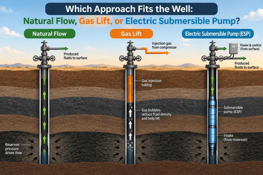
Natural flow uses energy already available in the reservoir and wellbore. Gas lift adds injected gas to reduce the density of the tubing fluid column. An ESP adds mechanical energy downhole through a multistage centrifugal pump.
Each method changes the pressure relationship between the reservoir, perforations, tubing, and surface facilities. That pressure relationship is the core of lift design.
🪨 Understand Where the Energy Comes From
Oil and gas enter a well because reservoir pressure exceeds the pressure at the sandface, the point where fluid moves from the formation into the wellbore. The greater the useful pressure drawdown, the more strongly the reservoir may deliver fluid—within limits set by rock and fluid behavior.
Once fluid enters the well, it must overcome pressure losses on its way to the separator. Those losses include hydrostatic head, friction, acceleration effects in multiphase flow, and surface backpressure.
Artificial lift does not create hydrocarbons in the reservoir. It lowers the flowing bottomhole pressure or improves the lifting path so the reservoir can deliver fluids at a useful rate.
📉 Read the Inflow Performance Relationship
An inflow performance relationship, often called an IPR, describes how well liquid production rate changes with flowing bottomhole pressure. It represents the reservoir and completion side of the production system.
For a productive well, lowering bottomhole pressure generally increases inflow. However, the relationship may be nonlinear, especially when gas comes out of solution near the wellbore, when water and oil move together, or when completion damage limits flow.
An IPR is not a permanent property. Reservoir depletion, changing water saturation, scale, fines migration, stimulation, and perforation condition can all shift it. Lift selection based on an outdated IPR can be misleading.
📈 Pair Inflow With Outflow
The tubing and surface network impose an outflow requirement: for each liquid rate, they require a certain bottomhole pressure to carry the fluid to the separator. This is commonly represented by tubing performance or a vertical lift performance curve.
The operating point is where the IPR and outflow curves intersect. At that point, the reservoir can supply exactly the rate the wellbore and surface system can transport.
Natural flow is feasible only when this intersection provides an acceptable rate without artificial lift. Gas lift and ESPs modify the outflow side, shifting the operating point toward a lower flowing bottomhole pressure and potentially a higher rate.
🌊 Know What Natural Flow Really Means
A naturally flowing well has enough available reservoir energy to move produced fluids through the completion, tubing, flowline, and surface choke to the separator. The energy may come from gas expansion, solution-gas drive, water influx, gas-cap support, or a combination of mechanisms.
Natural flow is often associated with early field life, but the term says nothing about the well’s overall productivity. A naturally flowing well can still be constrained by high backpressure, restrictive tubing, formation damage, or unstable multiphase behavior.
It is best understood as a pressure-balance outcome, not as a permanent well classification.
✅ See Why Natural Flow Is Attractive
When it is stable and sufficient, natural flow is operationally simple. No downhole pump, power cable, or injection-gas supply is needed specifically to lift liquids.
- It usually has fewer artificial-lift components to install and monitor.
- It avoids electrical load associated with a downhole motor.
- It can reduce routine lift-system maintenance and intervention exposure.
- It preserves flexibility while reservoir energy remains adequate.
These advantages do not mean a naturally flowing well should always be left untouched. A surface constraint or poor tubing design can waste available reservoir energy.
⚠️ Recognize When Natural Flow Falls Short
Natural flow becomes inadequate when the pressure available at the sandface can no longer overcome the hydrostatic weight and friction of the produced fluid stream while meeting required surface pressure.
Increasing water cut is a common reason. Water is generally denser than oil, so a larger water fraction can increase the hydrostatic burden in the tubing. Depletion also reduces the pressure available to sustain flow.
Other warning signs include declining wellhead pressure, unstable rates, frequent liquid loading, a choke opened near its practical limit, or a calculated operating point that falls below the target liquid rate.
🛢️ Identify Liquid Loading and Flow Instability
In gas-rich wells, the gas rate may be insufficient to continuously carry produced liquids to surface. Liquids accumulate in the tubing, raising the hydrostatic pressure until flow weakens or stops. Later, gas may build up and unload the liquid slug abruptly.
This cycling is not the same as healthy natural flow. It can create variable separator conditions, erode equipment, complicate measurement, and leave production below potential.
Gas lift can sometimes help stabilize the tubing column, but the design must account for the well’s gas-liquid behavior rather than simply adding gas at the highest available injection pressure.
💨 Define Gas Lift in Practical Terms
Gas lift injects compressed gas into the production tubing through valves installed in side-pocket mandrels, typically as part of a gas-lift completion. The injected gas mixes with produced fluids and lowers the average density of the tubing fluid column.
A lighter fluid column requires less pressure at the bottom of the tubing to lift a given volume to surface. This can lower flowing bottomhole pressure and increase reservoir inflow.
Gas lift is therefore a gas-assisted pressure reduction method. It is not a pump: it does not directly displace liquid with a moving mechanical element.
🔧 Follow the Gas-Lift Mechanism Downhole
During unloading, gas-lift valves at different depths can help displace completion fluids and establish injection at the intended operating valve. Once the well reaches operating conditions, injection gas should enter at a suitable depth and rate for efficient lifting.
Deeper injection generally reduces more of the hydrostatic column, which can improve lift performance. But injection depth is limited by available casing pressure, valve behavior, tubing pressure, well geometry, and the ability to unload the well.
A design that looks ideal on paper may not be operable if the compressor cannot provide enough pressure to unload or sustain injection at the planned depth.
🧪 Account for Gas-Lift Gas Quality and Supply
Gas lift depends on a dependable source of injection gas and compression. In a field with abundant produced gas and a functioning compression network, gas lift may fit naturally into the infrastructure.
The gas must also be compatible with the system. Corrosive components, liquids, solids, or unstable supply quality can affect compressors, valves, flowlines, and allocation accuracy.
Injection gas has an opportunity cost. Gas used for lift may otherwise be sold, reinjected, used as fuel, or needed for gas handling constraints. The engineering comparison should include the value and availability of that gas, not merely the wellhead liquid rate.
👍 Match Gas Lift to Its Strengths
Gas lift is often valued for operating flexibility. Injection rate can be adjusted from surface, and wells can be optimized as reservoir conditions change. It can also tolerate deviated wells and some solids better than tightly clearance-sensitive pumping systems.
It is commonly attractive where several wells share a gas-lift distribution system and where high liquid rates, moderate-to-deep settings, or changing production conditions require adjustable lift.
For offshore or remote facilities, the decision is more nuanced: shared infrastructure can be beneficial, but compression reliability and platform space may become decisive constraints.
🚫 Understand Gas-Lift Limitations
Gas lift requires compression, distribution piping, control equipment, and allocation discipline. A compressor outage can affect many wells at once, making system reliability a field-level issue rather than a single-well issue.
Too little injection gas may fail to reduce hydrostatic head sufficiently. Too much gas can increase friction, raise surface gas-handling demand, cause unstable operation, or divert lift gas from wells where it would create more production.
Gas lift also cannot compensate for every poor inflow problem. If formation productivity is very low, reducing tubing pressure may produce only a small rate increase.
⚡ Define an Electric Submersible Pump
An ESP is a downhole centrifugal pumping system, normally comprising a multistage pump, intake or gas-handling equipment, seal section, motor, power cable, and surface electrical controls. The motor turns the pump stages at high speed, adding pressure to the produced fluid.
Each stage contributes a relatively small pressure increase; many stages in series provide enough total head to lift fluid from the pump setting depth to surface and overcome downstream pressure requirements.
In simple terms, an ESP is like placing a compact stack of spinning water-lift stages deep in the well. Its performance depends strongly on the fluid it receives and the operating rate selected.
🌀 Read the ESP Pump Curve
An ESP pump has a characteristic relationship between flow rate, head, efficiency, and power demand. “Head” is the pressure increase expressed as an equivalent fluid height, and it changes with fluid density.
Operating too far below the preferred rate can encourage recirculation, heating, vibration, and reduced efficiency. Operating too far above it can reduce developed head and increase mechanical loading.
The design goal is not merely to install enough stages. It is to place the expected operating range in a stable, efficient part of the pump curve while retaining room for likely changes in inflow and water cut.
📍 Choose Pump Setting Depth Carefully
The pump intake should usually be set deep enough to create the desired drawdown and maintain sufficient intake pressure. A deeper setting can reduce the pressure left below the pump, but it also introduces completion, cable, temperature, and intervention considerations.
Setting depth must respect casing geometry, perforation location, dogleg severity, packers, tubing forces, and the possibility of future workover operations. In highly deviated or horizontal wells, installation and cable protection require particular attention.
A pump set too shallow may leave useful drawdown unrealized. A pump set too deep without adequate intake pressure may face gas interference or poor operating conditions.
🌫️ Manage Free Gas at the Pump Intake
Centrifugal pumps are designed primarily to move liquid. When substantial free gas enters the pump, gas can separate inside the stages, reducing head generation and causing erratic behavior. In severe cases, the pump can experience gas lock.
Gas separators, gas handlers, special pump designs, and careful setting depth can improve tolerance, but none removes the need to understand intake conditions. The relevant issue is not only total gas-oil ratio; it is how much gas is free at pump intake pressure and temperature.
Lowering intake pressure may increase drawdown, yet it can also release more gas from the liquid. That tradeoff is central to ESP design.
💧 Consider Water, Viscosity, and Emulsions
High water cut does not automatically rule out an ESP. In many wells, ESPs lift large liquid volumes effectively as water production increases. But fluid properties influence head requirements, power, corrosion risk, scaling tendency, and pump operating range.
High-viscosity oil can reduce pump performance and efficiency relative to water-based test assumptions. Stable emulsions may behave differently from either clean oil or clean water, and viscosity can change with temperature.
Design calculations should use representative fluid-property data across the expected operating envelope. A single early-life fluid sample may not represent late-life conditions.
🏗️ Match ESPs to Their Strengths
ESPs are especially useful when a well has strong liquid inflow potential and needs a substantial pressure boost to move high liquid volumes to surface. Their compact downhole footprint can be valuable where a surface pumping unit would be impractical.
Variable-speed drives can allow operators to adjust pump speed as inflow changes. This creates operational flexibility, although every speed change must remain within electrical, mechanical, and hydraulic limits.
An ESP is often a powerful choice, but it is not automatically the best choice for every high-rate well. Gas fraction, solids, power quality, intervention cost, and expected production decline can change the answer.
🧱 Respect ESP Failure Drivers
ESP reliability is sensitive to installation quality and operating environment. Common challenges include free gas, solids abrasion, scale deposition, corrosion, overheating, cable damage, electrical faults, and operation far from the preferred flow range.
Low flow can reduce cooling around the motor. High solids can wear stages and thrust components. Scale can restrict passages or impair performance. These are not isolated equipment problems; they often reflect reservoir, fluid-treatment, or operating-control issues.
A failure review should look beyond the retrieved pump. The key question is what well condition, design assumption, or operational event created the damaging environment.
⚖️ Compare the Three Approaches
| Approach | Primary mechanism | Often fits when | Main constraint |
|---|---|---|---|
| Natural flow | Uses reservoir and produced-gas energy | Reservoir pressure and wellbore hydraulics sustain target rate | Declining pressure or rising liquid head |
| Gas lift | Reduces average tubing-fluid density with injected gas | Injection gas and compression are available; flexibility is valuable | Gas supply, compression, distribution, and allocation |
| ESP | Adds downhole pressure with a centrifugal pump | High liquid rate and substantial lift requirement are expected | Free gas, solids, power, and intervention consequences |
This table is a screening aid, not a design rule. A field may use all three approaches at different stages of life or in different well groups.
🧾 Begin With Reliable Well Data
Artificial-lift selection is only as credible as the data used to model it. Start with recent production rates, water cut, gas-oil ratio, flowing pressures, temperatures, fluid samples, completion schematic, deviation survey, and surface operating pressures.
Pressure data deserve special scrutiny. A tubing-head pressure without separator pressure, choke condition, and measurement context may not describe the actual system. Similarly, a liquid test rate without stabilized conditions can distort an IPR or pump selection.
- Verify gauge locations and calibration status.
- Distinguish measured values from estimated values.
- Record whether rates are stabilized or transient.
- Update fluid properties when water cut or operating temperature changes.
🧠 Use Nodal Analysis Instead of Guesswork
Nodal analysis divides the production system into components and calculates pressure losses through each one. The chosen “node” may be the sandface, pump intake, wellhead, or another useful location.
It reveals whether the principal restriction is in the reservoir, perforations, tubing, choke, flowline, separator pressure, or the proposed lift equipment. This prevents a common mistake: installing a powerful lift system to solve a surface bottleneck.
Models require validation against field measurements. A calibrated model is more useful than a complex but unverified one.
🎯 Define the Production Objective First
Different objectives can lead to different lift choices. One well may need maximum near-term liquid rate. Another may need stable production within gas-handling limits, reduced water disposal burden, or low intervention risk in an expensive workover environment.
Define the target in operational terms: expected liquid range, minimum acceptable oil rate, allowable gas injection, available electrical power, separator constraints, and acceptable decline response.
Without a stated objective, “optimization” can become shorthand for maximizing one variable while creating trouble elsewhere in the production system.
🔄 Plan for the Well’s Changing Life
A well’s best lift method can change over time. Early natural flow may give way to gas lift as pressure declines. Later, an ESP may be considered if liquid volumes and power access support it. In another field, the sequence may be different.
Water cut, gas availability, reservoir pressure, solids production, and workover opportunities should all be included in a life-of-well view. Designing only for the first few months can lock the asset into costly changes later.
Forecasts are uncertain, so scenario ranges are more honest than a single precise future profile. Test low, base, and high inflow cases as well as different water-cut and gas-fraction conditions.
🏭 Include Surface Facilities in the Answer
A lift method changes more than the well. Gas lift can increase produced gas volume at surface and require compression, metering, and separation capacity. ESPs increase electrical demand and may increase liquid throughput beyond flowline, separator, water-treatment, or disposal limits.
Natural flow may appear cheapest at the well but may still be restricted by excessive backpressure in a shared flowline or separator. Sometimes reducing a surface bottleneck provides more value than changing downhole lift.
The well and facilities are one hydraulic system. Treating them separately is a frequent source of disappointing results.
💰 Compare Value Beyond Initial Cost
Economic comparison should include installation cost, energy or fuel use, compression needs, maintenance, expected run life, intervention cost, deferred production during failures, and the value of incremental oil and gas.
A low-cost installation can be poor value if it creates frequent interventions or leaves large production potential unrealized. Conversely, the most capable equipment may not be justified if the well’s inflow is modest or decline is rapid.
Use field-specific assumptions and update them as actual operating experience becomes available. Economic rankings can shift when power reliability, rig access, gas value, or water-handling costs change.
🦺 Put Safety and Integrity Into the Design
Artificial lift introduces specific integrity and safety considerations. Gas lift requires management of high-pressure gas, valves, injection lines, and compressor systems. ESPs require electrical isolation, cable handling, motor protection, and safe lifting operations during installation and retrieval.
Both methods interact with corrosion, scale, pressure containment, and produced-fluid hazards. If a well has known integrity concerns, the lift design must not increase annular pressure risk or compromise barrier management.
Site procedures, equipment ratings, and operating limits must follow the applicable company requirements and local regulations. This article describes engineering principles, not a substitute for a site-specific safety review.
🔍 Watch for Diagnostic Signals
Production surveillance turns lift selection into ongoing management. For gas lift, useful signals include injection rate and pressure, casing pressure, tubing pressure, valve behavior, production response, and compressor performance.
For ESPs, operators watch motor current, voltage, frequency, intake and discharge pressures where available, vibration indicators, wellhead conditions, fluid rate, and changing water cut. Trends often reveal deterioration before a complete failure occurs.
Interpret signals in context. A falling ESP current might indicate reduced fluid load, but it could also reflect gas interference or a changing electrical condition. One measurement rarely tells the whole story.
🛠️ Avoid Common Selection Mistakes
Several errors recur because they simplify a multi-variable problem too aggressively.
- Choosing from initial rate alone: early tests may not represent future pressure, water cut, or gas behavior.
- Ignoring surface backpressure: a restrictive choke, flowline, or separator can dominate performance.
- Assuming more lift is always better: excessive drawdown can increase gas interference, solids production, water production, or facility loading.
- Using generic pump or valve assumptions: actual fluid properties and well geometry matter.
- Failing to plan surveillance: a design cannot remain optimized if operating data are not reviewed.
🧩 Work Through a Hypothetical Example
Consider a hypothetical mature oil well whose natural rate has declined as reservoir pressure falls and water cut rises. The well still has reasonable inflow, but its flowing bottomhole pressure is too high to meet the desired liquid target.
If the field has spare compression capacity and a reliable gas-lift network, gas lift may lower the hydrostatic head with relatively modest downhole hardware changes. The design would test whether injection can reach sufficient depth and whether added gas stays within separator and compression limits.
If the well has strong liquid productivity, limited free gas at a suitably deep intake, and dependable power, an ESP may provide a larger pressure boost. The comparison would then include expected pump operating range, gas-handling needs, workover cost, and the ability of facilities to handle higher liquid volume.
If modeling shows that a high separator pressure is the main restriction, neither option should be selected before assessing that surface bottleneck. The correct answer may be a facilities change rather than a new lift system.
🗺️ Use a Practical Screening Sequence
- Confirm the production objective and facility constraints.
- Gather and quality-check current well, fluid, completion, and surface data.
- Build or update the IPR and tubing/surface outflow model.
- Test whether natural flow can meet the target under realistic conditions.
- Screen gas lift for injection-gas availability, pressure, depth, and system capacity.
- Screen ESPs for inflow, intake gas fraction, fluid properties, power, geometry, and intervention implications.
- Compare lifecycle economics, reliability exposure, and operational flexibility.
- Select an operating envelope and surveillance plan, not just a piece of equipment.
This sequence encourages disciplined engineering while leaving room for field experience and local constraints.
🏁 Choose the System That Fits the Whole Well
Natural flow is the preferred starting condition when reservoir energy and wellbore hydraulics can meet the production objective safely and stably. Its simplicity is valuable, but it should be verified through current pressure and performance data.
Gas lift fits wells and fields where injection gas, compression, and distribution infrastructure are available and where adjustable reduction of tubing-fluid density is useful. Its strength is flexibility; its dependency is the gas-lift network.
ESPs fit many high-liquid-rate applications that need substantial added pressure, provided free gas, solids, fluid properties, electrical supply, and intervention risk are managed. Their strength is hydraulic capability; their dependency is operating in a suitable pump environment.
The best artificial-lift decision comes from matching reservoir inflow, wellbore hydraulics, fluids, facilities, and lifecycle risk—not from choosing the most familiar technology.
Revisit that match as the well changes. A well is not static, and neither should its production strategy be. 🛢️⚙️📈