
A producing oil well can look deceptively simple from the surface: a wellhead, a few valves, pipelines, and perhaps a pumping unit moving rhythmically up and down. Yet the first force that brings fluids toward the well is usually not the surface equipment. It is energy stored deep inside the reservoir.
When a well is opened, pressure near the wellbore falls. Fluids in the surrounding rock respond to that pressure difference, moving through microscopic connected pore spaces toward the lower-pressure area. The question is what supplies enough energy to keep that movement going as production removes oil, gas, and water.
This is the practical meaning of a reservoir drive mechanism. It describes the dominant source, or combination of sources, of energy that displaces reservoir fluids and sustains production.
For students, drive mechanisms turn pressure-volume behavior into a physical story. For working professionals, they shape forecasts, surveillance plans, completion choices, facility design, recovery strategy, and the decision of when artificial lift or injection is needed.
🧭 Reservoir Drive Is the Energy Behind Production
A reservoir is a volume of porous, permeable rock containing fluids under pressure. Oil does not normally sit in underground caverns waiting to drain; it occupies pores between mineral grains, alongside water and sometimes gas.
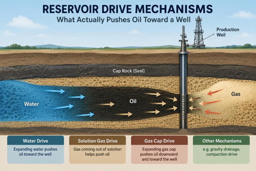
A drive mechanism is the process that provides energy as fluids are produced. That energy may come from expanding fluids, water entering the reservoir, gas released from oil, a growing gas cap, gravity segregation, rock compaction, or injected fluids.
Most reservoirs show more than one mechanism. Engineers identify the dominant drive because it most strongly controls pressure decline, water production, gas behavior, and expected recovery.
📉 The Pressure Drawdown That Starts Flow
Production begins with a pressure difference called drawdown: reservoir pressure is higher than flowing pressure at the sandface, the interface where the well communicates with the formation. Fluids move toward the well because flow follows a pressure gradient.
Think of a sponge saturated with liquid. Squeezing or lowering pressure at one point does not instantly empty every pore; fluid must travel through a tortuous network. In reservoirs, permeability, fluid viscosity, relative permeability, and completion quality all affect that travel.
Drawdown alone is not a long-term energy source. If no fluid or rock expansion offsets produced volume, average reservoir pressure declines rapidly and the well eventually cannot deliver fluids efficiently.
🪨 Pore Space, Saturation, and Connected Flow Paths
Two rock properties set the stage. Porosity is the fraction of rock volume made of pore space. Permeability describes how readily connected pores transmit fluid.
Each fluid occupies part of that pore space. Water saturation is the fraction occupied by water, oil saturation is the fraction occupied by oil, and gas saturation is the fraction occupied by gas. These saturations change as a reservoir produces.
Oil need not be mobile simply because it is present. Some oil is trapped by capillary forces at the pore scale, while water or gas may have easier flow paths. Drive mechanisms matter partly because they change saturations and therefore change which phases can move.
🧪 Compressibility: Small Changes With Large Consequences
All reservoir materials compress or expand to some degree. Fluids expand as pressure falls, while pore volume and rock grains can compact. The amount of volume change per unit pressure change is described by compressibility.
Liquid water and undersaturated oil are only slightly compressible, so their expansion often provides limited energy by itself. Gas is much more compressible and can expand substantially, which is why free gas can become a powerful drive source.
Even so, high gas expansibility does not automatically mean high oil recovery. Gas may bypass oil, channel through high-permeability layers, or reduce oil relative permeability near the well.
🌊 Water Drive: An Aquifer Supporting the Reservoir
In a water-drive reservoir, an aquifer—a water-bearing rock body hydraulically connected to the oil zone—expands and moves water into the reservoir as fluids are removed. This incoming water can replace part of the produced volume and help preserve pressure.
The aquifer may lie below the oil as bottom water or extend laterally as edge water. Its effectiveness depends on size, permeability, pressure communication, geometry, and the production rate imposed on the reservoir.
A strong water drive can sustain production for a long period, but the same water that provides pressure support can eventually reach wells and increase water handling requirements.
💧 Strong and Weak Aquifers Behave Differently
A strong aquifer responds readily to pressure depletion and may keep reservoir pressure relatively stable. A weak or restricted aquifer contributes less water, so pressure can decline more noticeably.
“Strong” does not mean universally desirable. Rapid water encroachment may reach producers early, leaving movable oil behind in less-swept zones. Conversely, a weak aquifer may offer less pressure support but delay water breakthrough in selected wells.
Reservoir engineers assess aquifer behavior using pressure trends, water-rate history, fluid contacts, material balance, production response, and reservoir simulation. No single observation provides a complete diagnosis.
🚰 Water Encroachment and the Moving Contact
As water enters an oil reservoir, the oil-water contact may rise or advance toward producing wells. This movement is called water encroachment. It is a displacement process, not simply water appearing at random.
In an idealized, uniform reservoir, water would sweep oil in a relatively orderly front. Real formations are layered and heterogeneous, so water commonly advances faster through more permeable streaks while bypassing oil in tighter intervals.
Early water production can therefore indicate a nearby contact, a high-permeability pathway, a completion interval too low in the structure, or a mechanical problem. The remedy depends on the cause.
🫧 Solution-Gas Drive: Gas Comes Out of Oil
Crude oil often contains dissolved natural gas at reservoir conditions. As pressure falls below the bubble-point pressure, gas begins to evolve from solution, forming separate gas bubbles in the pore space.
Those bubbles expand as pressure continues to decline. Their expansion can help push oil, particularly during early depletion, but the drive usually loses efficiency as gas saturation grows and oil mobility falls.
Solution-gas drive is also called depletion drive. It commonly produces substantial gas-oil ratio changes and relatively fast pressure decline when little external water support exists.
⚠️ Why Free Gas Does Not Always Help Oil Flow
At first, newly formed gas bubbles may remain disconnected and immobile. Once gas saturation exceeds a critical level, the bubbles connect and gas becomes mobile. It can then flow more readily than oil toward the well.
This creates a familiar challenge: gas near the well may occupy flow channels that oil needs. The well can produce increasing gas volumes while oil rate declines, even though oil remains in the reservoir.
Producing too aggressively below bubble point can intensify this effect in some reservoirs. Appropriate drawdown must balance near-term rate against long-term fluid mobility and pressure management.
🎈 Gas-Cap Drive: Expansion From Above the Oil
A gas-cap-drive reservoir contains a free-gas zone above the oil before significant production begins. As reservoir pressure falls, the gas cap expands downward and laterally, displacing oil toward producing wells.
Gas-cap drive generally provides better pressure support than solution-gas drive because a substantial, connected gas volume is already present. Still, its performance depends strongly on structure, vertical permeability, well placement, and gas production control.
If wells are completed too near the gas-oil contact or drawn down too hard, gas can cone into the well. This may reduce oil productivity and waste gas that could otherwise support the reservoir.
🧱 Gas Coning and Cresting Near Wells
Gas coning occurs when the gas-oil contact is pulled upward locally toward a producing well. In deviated or horizontal wells, the same phenomenon may be described as gas cresting.
The risk rises when vertical drawdown is high, the completion is close to the contact, vertical permeability is favorable to gas movement, or production rates exceed what the reservoir geometry can support.
Reducing rate may stabilize the interface, but it is not a universal cure. Completion placement, selective isolation, well trajectory, and reservoir pressure management can also be decisive.
🏔️ Gravity Drainage: Density Does Useful Work
Gravity drainage uses the density difference between reservoir fluids. Gas tends to rise, water tends to settle, and oil occupies an intermediate position. Given sufficient vertical permeability and structural relief, these tendencies can help displace oil downward or laterally toward wells.
This mechanism is especially relevant in thick, dipping, fractured, or vertically connected reservoirs. It can work with a gas cap, water influx, or injected gas rather than acting alone.
Gravity drainage is often more efficient when production rates are controlled so that fluids segregate rather than becoming strongly mixed by rapid flow. The best rate is reservoir-specific, not a fixed rule.
🪨 Compaction Drive: The Rock Also Releases Energy
When pressure declines, effective stress on the rock framework rises. Some formations compact, reducing pore volume and expelling fluids. This is known as compaction drive.
Compaction can contribute meaningful energy in compressible formations, but it also introduces risks. Reservoir compaction may cause surface subsidence, casing deformation, changes in permeability, sand production, or damage to wells and facilities.
Engineers do not treat compaction as free energy. It requires geomechanical assessment and careful monitoring because the same deformation that helps expel fluids can compromise field integrity.
🔄 Combination Drive Is More Common Than Pure Cases
Textbooks often present water drive, gas-cap drive, solution-gas drive, gravity drainage, and compaction drive as distinct categories. Real reservoirs frequently combine them.
For example, a reservoir may begin with a gas cap and a modest edge aquifer. Later, water influx may become more visible while localized solution gas develops around depleted wells. Different parts of the same field may behave differently.
Calling a reservoir “water drive” is therefore a useful shorthand, not a claim that no other energy exists. Field decisions should be based on measured behavior, not labels alone.
📊 Pressure Behavior Offers the First Clues
Average reservoir pressure is one of the most informative surveillance measurements. A relatively stable pressure trend during production can suggest substantial support from water influx, gas-cap expansion, or injection.
A rapid decline may point to limited external support and depletion-dominated behavior. But pressure data must be interpreted carefully: shut-in duration, gauge quality, wellbore effects, compartmentalization, and uneven depletion can distort a simple reading.
Pressure is best viewed alongside production volumes, fluid ratios, contact movement, and geological understanding. One data point is a clue; a consistent history is evidence.
📈 Production Signatures Help Identify the Drive
Rate and fluid-ratio trends provide additional signatures. Increasing water cut—the water fraction of total liquid production—can indicate advancing water, though it may also reflect channeling or completion-related issues.
Rising gas-oil ratio may accompany solution-gas liberation, gas-cap encroachment, or gas breakthrough from an injection process. A falling oil rate can result from declining pressure, rising water saturation, gas interference, equipment limits, or all of these together.
| Observed trend | Possible interpretation | Why confirmation is needed |
|---|---|---|
| Pressure remains relatively supported | Active aquifer, gas cap, or injection support | Compartments and measurement conditions can mask decline |
| Water cut rises in selected wells | Water encroachment or high-permeability channeling | Completion leaks and behind-pipe flow can look similar |
| Gas-oil ratio rises sharply | Solution gas, gas coning, or gas breakthrough | Surface allocation and operating changes may affect reported ratios |
| Different wells show very different pressures | Barriers, faults, or poor communication | Transient wellbore effects must be separated from reservoir effects |
🧮 Material Balance Connects Produced Volume to Energy
Material balance is an accounting framework for the reservoir. It relates underground withdrawals of oil, gas, and water to expansion of fluids and rock, water influx, and any injected volumes.
Its central question is simple: when a barrel of fluid is produced underground, what volume change replaced it? The answer reveals which mechanisms are likely contributing energy.
Material balance depends on representative pressure and reliable production data. Errors in fluid properties, allocation, or pressure averages can lead to misleading conclusions, so it is commonly used with other methods.
🗺️ Geological Architecture Controls Sweep
Drive energy is only useful where it can contact and displace oil. Faults, shale barriers, stratigraphic pinch-outs, fractures, and permeability contrasts determine whether pressure support reaches all parts of the reservoir.
A large aquifer may support one compartment well while another compartment depletes rapidly behind a sealing fault. Similarly, injected water may preferentially move through a thief zone rather than sweeping lower-permeability rock.
Understanding architecture turns a broad drive concept into a field-specific model. Seismic interpretation, well logs, cores, pressure communication tests, and production history each contribute part of that model.
🧷 Relative Permeability Explains Multiphase Competition
When oil, water, and gas coexist, each phase flows less easily than it would alone. Relative permeability expresses this reduction in flow capacity for each phase at a given saturation.
As water saturation rises behind a waterflood or aquifer front, water relative permeability tends to increase while oil relative permeability decreases. The same principle applies when gas saturation grows near a producing well.
This is why pressure support and oil displacement are not identical. A reservoir can retain pressure yet produce oil poorly if the phase distribution makes oil relatively immobile.
🧲 Capillary Pressure Leaves Oil Behind
At the pore scale, interfaces between oil, water, and gas are influenced by surface tension and rock wettability. The resulting pressure difference is called capillary pressure.
Capillary forces can trap disconnected oil ganglia after water or gas passes through a pore network. This residual oil is a key reason that a natural drive may leave substantial oil in place even after economic production slows.
Wettability, pore geometry, fluid properties, and displacement rate all matter. A simple displacement sketch is useful for learning, but it cannot show every microscopic trapping process.
🚿 Waterflooding Extends Natural Water Support
When natural water influx is inadequate or poorly positioned, operators may inject water through dedicated wells. Waterflooding aims to maintain pressure and displace oil toward producers.
Injection pattern, rate, water quality, reservoir layering, and producer-injector communication all influence the result. Water that reaches a producer too quickly may signal a short circuit rather than efficient areal sweep.
Waterflooding is not guaranteed to improve every field. It requires compatible injection water, suitable injectivity, containment, facilities for produced water, and a credible understanding of where injected water will travel.
🌫️ Gas Injection Can Supply Pressure and Displacement
Gas injection may maintain pressure, expand a gas cap, or improve displacement under appropriate pressure and fluid-composition conditions. Depending on the system, injected gas may remain distinct from oil or become partly miscible with it.
Miscibility refers to conditions under which the gas and oil can mix extensively, reducing interfacial effects and potentially improving displacement. Achieving and maintaining those conditions depends on reservoir pressure, temperature, oil composition, and injection-gas composition.
Gas has low density and viscosity compared with oil, so gravity override and early gas breakthrough are practical concerns. Mobility-control methods and thoughtful injection design may be needed.
⚙️ Primary, Secondary, and Tertiary Recovery Are Different Ideas
Primary recovery uses natural reservoir energy, sometimes aided by artificial lift at the well. Secondary recovery commonly refers to water or gas injection intended mainly for pressure maintenance and macroscopic displacement.
Tertiary recovery, often grouped under enhanced oil recovery, involves processes designed to alter fluid behavior or improve microscopic displacement, such as thermal, chemical, or miscible methods. The boundaries can blur in practice.
Artificial lift should not be confused with a reservoir drive mechanism. A pump can lower flowing wellbore pressure and help a well lift fluids to surface, but it does not by itself replace reservoir energy or sweep oil through the formation.
🏗️ Well Placement Must Respect Fluid Contacts
Where a well is placed relative to gas-oil and oil-water contacts strongly affects coning risk and productive life. A completion near bottom water may see early water production; one near a gas cap may see early gas entry.
Horizontal wells can expose more reservoir rock and reduce localized drawdown when designed well. However, a long lateral also encounters more heterogeneity and may intersect intervals with different fluid risks.
Placement is a tradeoff between maximum reservoir contact, structural position, completion reliability, and operational flexibility. The best location cannot be selected from a structural map alone.
🎛️ Production Rate Can Change the Drive Response
Higher production rates increase drawdown and can deliver stronger short-term output. They can also accelerate gas liberation, water or gas coning, fines movement, sand production, and uneven depletion in sensitive reservoirs.
Lower rates may improve stability around fluid contacts but reduce near-term cash flow and may not be necessary in every formation. Rate management is therefore an optimization problem, not a blanket instruction to produce slowly.
Engineers use pressure surveillance, well tests, production logging, and model forecasts to evaluate whether a rate change is improving recovery or merely changing the timing of production.
🔍 Surveillance Turns Assumptions Into Decisions
Reservoir models begin as interpretations. Surveillance tests those interpretations against field behavior. Useful measurements can include shut-in pressures, flowing pressures, rates, water cut, gas-oil ratio, injected volumes, fluid samples, and production logs.
Time-lapse saturation monitoring and pressure-interference observations can add valuable information where available, but every tool has resolution and cost limits. A practical program focuses on uncertainties that would change a decision.
For example, distinguishing water coning from a leaking completion matters because the corrective actions are entirely different. Better data is valuable when it narrows that choice.
🚧 Common Misconceptions About Reservoir Energy
- “Oil is sucked out of the ground.” A well creates lower pressure, but reservoir fluids are pushed toward it by pressure gradients and expansion energy.
- “A high-pressure reservoir always has high recovery.” Recovery also depends on sweep, trapping, heterogeneity, and fluid mobility.
- “Water production means the reservoir is finished.” Some water-drive fields remain productive for long periods, although water handling may become the economic constraint.
- “A pump creates reservoir pressure.” Artificial lift helps lift produced fluids; injection and natural expansion affect reservoir pressure support.
- “One drive mechanism explains every well.” Local geology and completion behavior can make individual wells respond differently.
🧠 A Simple Hypothetical Field Example
Imagine an oil reservoir with a small initial gas cap and a connected edge aquifer. Early production causes modest pressure decline, while gas-oil ratio remains manageable and water cut is low.
After several years, wells near the flank show rising water cut, while crest wells show increasing gas-oil ratio. The field is not necessarily changing from one drive mechanism to another; rather, different components of a combination drive are becoming visible in different locations.
A sensible response might include reviewing completion depths, mapping pressure by area, checking well integrity, assessing water movement, and forecasting alternatives such as controlled production rates or targeted injection. The data, not the label, should guide the plan.
🧩 The Core Principle: Volume Replacement Governs Depletion
Every producing reservoir must balance underground withdrawals with some form of volume replacement. That replacement may come from expanding dissolved gas, a gas cap, water influx, rock compaction, injected fluids, or several mechanisms working together.
The quality of a drive is not measured only by how well it maintains pressure. A favorable mechanism must also contact oil, move it through the rock, and avoid excessive bypassing, early breakthrough, or damaging geomechanical effects.
Understanding reservoir drive mechanisms means connecting pressure behavior to rock properties, fluid saturations, geological architecture, wells, and operations. That connection is what turns production data into an explanation of what is actually pushing oil toward a well.
Oil reaches a well not because the well simply pulls it upward, but because reservoir energy and pressure gradients move fluids through rock—and recovery depends on how effectively that energy sweeps the oil. 🛢️🪨📈