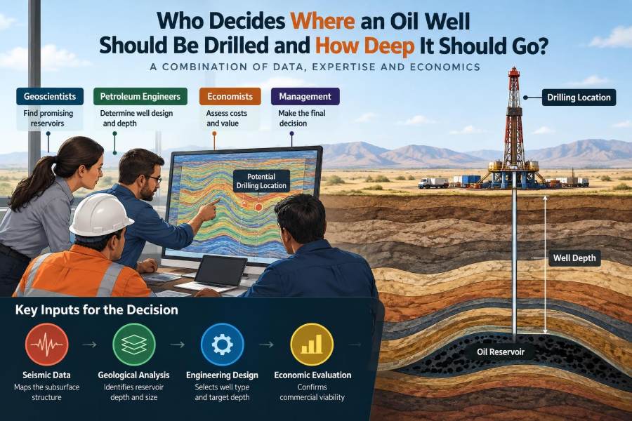

A drilling rig on the horizon can make the decision look simple: someone found oil, chose a point on a map, and told the crew to drill. In reality, the location of that rig may represent years of geological interpretation, engineering design, environmental review, commercial analysis, and risk discussion.
A well drilled a few hundred metres from the best part of a reservoir can produce far less than expected. A well that reaches the right rock at the wrong angle may leave valuable hydrocarbons unrecovered. And a technically promising target can still be rejected if it cannot be drilled and operated safely.
That is why the question is not answered by one person or one dataset. An oil well is the result of a structured, multidisciplinary decision process in which the subsurface target, surface constraints, drilling limits, and economic case all have to align.
For students, this process reveals how petroleum engineering fits with geoscience. For working professionals, it is a reminder that a well location is not a fixed geological fact; it is a carefully managed decision under uncertainty.
🧭 The short answer: a team decides, not a single job title
The person who ultimately approves a well may be an asset manager, operating company executive, or project decision authority. But that approval is built from recommendations made by a much wider team.
Geoscientists define the likely subsurface opportunity. Reservoir engineers estimate what may be recovered. Drilling engineers determine whether the proposed path can be drilled safely. Production, facilities, environmental, commercial, land, and regulatory specialists test whether the plan works in the real world.
The best well location is usually a compromise that preserves reservoir value while remaining safe, practical, and economic.
🪨 Start with the petroleum system
Before selecting a well location, the team must establish whether a working petroleum system exists. This means considering a source rock that generated hydrocarbons, migration pathways, a porous reservoir rock, a sealing rock, and a trap that retained the accumulation.
A geological structure may look attractive on a seismic map, but a trap alone does not prove that oil or gas is present. Hydrocarbons must have been generated and migrated into it at the right time.
This early screening determines whether a prospect is worth detailed work. It also frames the most basic question: is the proposed well exploring for an undiscovered accumulation, or developing one already confirmed?
🔎 Exploration wells and development wells serve different decisions
An exploration well tests whether commercial hydrocarbons exist in a previously unproven prospect. Its location is often selected to answer several high-value geological questions at once, such as whether a closure contains hydrocarbons and whether the reservoir has usable quality.
A development well is drilled after an accumulation has been discovered and evaluated. Its purpose is generally to produce hydrocarbons, inject water or gas, manage pressure, or improve reservoir drainage.
Exploration wells tolerate more geological uncertainty because uncertainty is the reason for drilling them. Development wells use more field data, but they face a different challenge: placing each well where it adds enough recovery to justify its cost and interaction with existing wells.
📡 Seismic data provides the underground map
Seismic surveying sends controlled sound energy into the Earth and records reflections from boundaries between rock layers. Interpreters use those reflections to map faults, folds, unconformities, and likely reservoir horizons.
Seismic does not directly show oil. It shows contrasts in rock properties and travel time. Converting those measurements into a reliable depth map requires assumptions about seismic velocity, and those assumptions can be wrong or incomplete.
Still, seismic is often the central spatial dataset for selecting a target. It helps a team identify a structural high, avoid a fault, or plan a horizontal section that stays within a thin reservoir layer.
🧱 Well logs anchor interpretations to real rock
Seismic interpretation becomes more reliable when it is calibrated with nearby wells. Wireline logs measure properties such as natural radioactivity, electrical resistivity, density, neutron response, and acoustic travel time.
These measurements help identify rock types, estimate porosity, distinguish probable water-bearing and hydrocarbon-bearing intervals, and correlate reservoir layers across a field. Core samples, cuttings, pressure data, and fluid samples add direct evidence.
A nearby well is useful, but it is not a perfect answer. Reservoir quality can change sharply over short distances, especially in channels, reefs, fractured carbonates, and faulted formations.
🗺️ A subsurface target is more than a map point
When a team says a well will be drilled at a given location, it usually refers to more than one coordinate. The plan includes a surface location, a target point in the reservoir, and a planned well path connecting them.
The target may be defined as a three-dimensional window rather than a single dot. This window specifies acceptable position, depth, and sometimes inclination limits at the reservoir entry point.
For a vertical well, the surface and subsurface positions can be close. For a long horizontal or extended-reach well, they may be kilometres apart. Confusing these two locations can lead to poor early project discussions.
📏 Depth is measured in several different ways
“How deep?” has no single universal answer. A rig measures measured depth, or MD, along the actual wellbore. A deviated well can have a much larger measured depth than its vertical depth.
Geologists commonly work with true vertical depth, or TVD, which is the vertical distance from a reference datum. They may also use true vertical depth subsea, or TVDSS, to compare layers across offshore areas and changing surface elevations.
| Depth term | What it describes | Why it matters |
|---|---|---|
| Measured depth | Distance along the well path | Drilling length, time, and equipment reach |
| True vertical depth | Vertical distance to a point underground | Formation correlation and pressure interpretation |
| True vertical depth subsea | Vertical depth referenced to sea level | Comparing structures across different elevations |
A reported total depth may mean the planned bottom of the hole, the deepest reservoir target, or the deepest geological objective. Engineers must state the reference clearly.
🏔️ Structure often controls the first target choice
In a conventional trapped accumulation, hydrocarbons are often buoyant relative to formation water. Oil and gas may therefore accumulate toward the higher parts of a sealed structure, while water occupies lower parts.
That makes a structural crest attractive, but “drill the highest point” is not a universal rule. The crest may be faulted, poorly imaged, too close to a gas cap, or distant from the best-quality reservoir rock.
Teams map contacts, such as the oil-water contact, and quantify uncertainty around their depth. A well placed too low may encounter water earlier than expected; one placed too high may encounter less oil column or unwanted gas.
🧽 Reservoir quality can outweigh structural height
A reservoir is not valuable simply because it contains hydrocarbons. It must have sufficient pore space and permeability, meaning the ability for fluids to flow through connected pores.
In some reservoirs, the highest structural position contains tight rock, while a lower area contains a thick, permeable sandstone body. A development team may select the lower location because it is more likely to deliver sustained production.
Reservoir heterogeneity matters especially in fluvial sandstones, layered turbidites, and carbonate systems. These rocks can contain barriers, baffles, fractures, or abrupt facies changes that alter how a well drains the field.
💧 Fluid contacts shape well placement
Oil, gas, and water may coexist in the same reservoir. Their boundaries are not always flat or perfectly sharp, but estimated fluid contacts are essential for choosing a completion interval.
A producer placed near an oil-water contact may face early water production. A well completed too close to a gas-oil contact may develop gas breakthrough. Both conditions can reduce oil rate, raise handling costs, and complicate operations.
Some wells are deliberately located near these zones. For example, an injection well may be placed to push fluids through the reservoir. The key is that placement follows a reservoir-management objective, not a generic preference.
🧪 Pressure data reveals how the reservoir communicates
Formation pressure measurements collected in wells can indicate fluid gradients, contacts, compartment boundaries, and whether fault blocks communicate. Pressure behavior also affects well-control design and casing requirements.
If two nearby areas have unexpectedly different pressures, a sealing fault or separate compartment may exist between them. That finding can change the estimated recoverable volume and may justify an additional appraisal well.
Pressure is dynamic. Production, injection, depletion, and aquifer support can change it over time. Development well locations should therefore be revisited as field behavior provides new evidence.
🧠 The geological model is an interpretation, not a photograph
Geoscientists combine seismic, well data, maps, and geological concepts into a three-dimensional earth model. The model represents the team’s best understanding of the subsurface, but it contains assumptions at every scale.
Fault locations may be uncertain, thin beds may fall below seismic resolution, and velocity errors can shift a predicted depth. Reservoir properties between wells must often be estimated rather than directly observed.
Good teams do not hide this uncertainty behind a single polished map. They identify what could be wrong, describe the potential consequence, and choose data or well designs that reduce the most valuable uncertainties.
🎯 A target window manages subsurface uncertainty
Rather than demanding that a bit hit one exact coordinate, teams define an acceptable target window. Its size depends on reservoir thickness, structural uncertainty, well objectives, and drilling capability.
A thick, uniform reservoir may allow a broad window. A thin oil rim between gas and water may require a narrow window and highly accurate geosteering. In that case, small depth errors have large production consequences.
Target design also includes directional constraints. A well may need to enter a layer at a particular angle, stay above a water contact, or cross fractures in a preferred orientation.
🛠️ Directional drilling separates the rig from the target
Modern wells can be drilled vertically, deviated at an angle, or horizontally through a reservoir. Downhole motors, rotary steerable systems, survey tools, and real-time measurements allow the trajectory to be controlled.
Directional drilling gives planners flexibility. A single onshore pad can reach several targets, while an offshore platform can access reservoir areas located away from the structure itself.
It also has limits. Greater departure can increase torque and drag, hole-cleaning challenges, hydraulic demands, casing-running difficulty, and cost. The most productive subsurface point is not automatically reachable with an acceptable drilling risk.
➖ Horizontal wells improve contact, but not automatically recovery
A horizontal well can expose a long length of reservoir to the wellbore. In suitable formations, that larger contact area can improve productivity and reduce drawdown near the well compared with a vertical well.
Horizontal placement is particularly useful in thin reservoirs, low-permeability formations, and layered reservoirs where a vertical well would contact only a limited productive interval. It can also help delay unwanted water or gas under favorable conditions.
However, long laterals can encounter variable rock quality, uneven inflow, mechanical restrictions, and completion complexity. Their value must be tested through reservoir simulation, productivity estimates, and realistic drilling design.
📈 Reservoir engineers turn rock data into recovery plans
Reservoir engineers estimate original fluids in place, forecast production, assess pressure support, and evaluate how wells influence one another. They use material-balance methods, decline analysis where production history exists, and numerical reservoir simulation when appropriate.
Simulation is not a crystal ball. It is a calculation framework whose results depend on input assumptions about permeability, relative permeability, aquifer behavior, faults, and operating strategy.
Its strength lies in comparing options consistently: for example, whether to add a producer on the flank, drill a horizontal infill well, or place an injector to support pressure.
💉 Injection wells are selected for sweep, not just access
Water injection and gas injection can help maintain pressure or displace hydrocarbons toward producing wells. An injector is therefore positioned to influence fluid movement across a meaningful portion of the reservoir.
Poorly placed injection can cause early breakthrough at producers, bypass oil in low-permeability zones, or inject into an unintended interval. The desired pattern depends on reservoir geometry, permeability direction, fractures, and existing well layout.
Injection decisions require special attention to containment. Engineers must evaluate caprock integrity, fault behavior, pressure limits, and the possibility of fluid movement into other formations.
🧭 Geosteering adjusts the plan while drilling
Even a carefully planned trajectory may need adjustment once drilling begins. Geosteering uses measurements while drilling, logging while drilling, cuttings, drilling response, and nearby data to keep a well within the intended reservoir zone.
For example, a horizontal well may approach the top of a thin sand body faster than predicted. The directional driller and geosteering team can alter inclination to remain in the most favorable interval, provided the well remains within approved operational limits.
This is not improvisation without discipline. Decisions are made against a predrill plan, real-time data, safety procedures, and a clear understanding of what the measurements can and cannot resolve.
🧱 Casing design can constrain the final depth
A well is drilled in sections, and steel casing is installed and cemented to isolate formations, support the borehole, and control pressure. Each casing point affects the remaining hole size and the options available below it.
Unexpected pressure, weak formations, lost circulation, or unstable shale can force a contingency casing string. That may leave insufficient hole size to reach a deeper objective or to run the planned completion.
Drilling engineers therefore design the well from the bottom upward as well as from the surface downward. A desired target depth is only meaningful if the casing and pressure plan can reach it safely.
⚠️ Pore pressure and fracture pressure set a safety envelope
Drilling fluid, commonly called mud, must exert enough pressure to prevent formation fluids from entering the wellbore. But excessive pressure can fracture the formation and cause losses of drilling fluid.
The range between pore pressure and fracture pressure is often called the operational pressure window. A narrow window makes drilling harder because the acceptable mud-weight range is small.
When this window is tight, a well may require more casing strings, specialized drilling practices, or a revised trajectory. No reservoir target justifies ignoring well-control and containment risks.
🌊 Surface location brings its own constraints
Onshore, the preferred surface site may conflict with homes, roads, protected areas, watercourses, cultural sites, property boundaries, or access limitations. In offshore settings, water depth, seabed conditions, shipping, pipelines, and platform capacity may matter.
Pad drilling can reduce the surface footprint by allowing multiple directional wells from one prepared location. It is often useful, but it does not eliminate the need to assess noise, traffic, emissions, waste handling, and local impacts.
A subsurface target may remain the same while the surface location shifts substantially to meet access, permitting, safety, or community requirements.
🌱 Environmental planning starts before the rig arrives
Environmental specialists identify potential impacts associated with site preparation, drilling fluids, cuttings, water use, emissions, noise, habitat disturbance, and eventual abandonment. Applicable rules differ by jurisdiction and project setting.
Planning may change the timing, site layout, transport route, fluid system, waste-management approach, or monitoring requirements. Sensitive seasons and protected habitats can affect when operations are feasible.
Environmental review is not separate from well design. A plan that cannot responsibly manage foreseeable impacts is not a complete drilling plan.
📜 Permits, mineral rights, and regulations matter
Before drilling, an operator generally needs the relevant rights to explore or produce and must meet permitting requirements set by the responsible authorities. The exact framework depends on the country, region, land ownership, and offshore jurisdiction.
Rules can govern well spacing, setbacks, reporting, blowout prevention, casing and cementing, water protection, emissions, plugging, and site restoration. These requirements influence both location and design.
For engineers, the practical lesson is simple: legal and regulatory constraints are engineering inputs. Discovering them late can delay a project or invalidate an otherwise sound design.
💰 The economic test asks whether value exceeds total cost and risk
A technically drillable well is not necessarily a commercial well. Decision-makers compare expected production and recovery with drilling, completion, tie-in, operating, abandonment, and risk-related costs.
They also consider uncertainty in reservoir size, well productivity, commodity prices, schedules, access to processing facilities, and future investment needs. The aim is not to claim certainty, but to understand the range of plausible outcomes.
A deeper target may contain more potential volume, yet be rejected if it requires a much more complex well with a weak chance of reaching commercial flow. Conversely, a modest infill well can be attractive when infrastructure already exists nearby.
🔄 Existing infrastructure changes the answer
Distance to pipelines, processing equipment, roads, power, water systems, and export routes can materially affect location choices. A field with spare facility capacity can support smaller additions that might not justify a standalone development.
In contrast, a remote discovery may require new pipelines, a platform, storage, or transport solutions. Those investments influence the number of wells needed and the threshold for proceeding.
Infrastructure should not force a poor reservoir decision, but it is part of the value equation. Petroleum engineering decisions are made across the full production system, not at the reservoir alone.
🤝 The decision process uses reviews and decision gates
Most organizations use staged reviews as a prospect or development matures. Early work may screen opportunities broadly; later work selects a concept, defines a drillable well, and authorizes expenditure.
At each stage, the team reviews assumptions, alternatives, uncertainties, costs, safety barriers, and decision criteria. Independent technical review can challenge optimistic interpretations and identify missing evidence.
This process can feel slow, but it prevents a high-cost well from being driven by one attractive map, one favorable forecast, or one department’s priorities.
📊 A simplified hypothetical example
Imagine a field where seismic suggests a reservoir at roughly 2,400 metres true vertical depth. The structural crest is the highest point, but it lies near a fault and close to a thin gas cap. A lower eastern area appears to contain cleaner sandstone with better predicted permeability.
A vertical well at the crest could test the trap, but a horizontal well from an existing pad could enter the eastern reservoir and remain above the estimated oil-water contact. The horizontal option costs more to drill, yet may access a longer productive interval and avoid a new surface location.
The team would compare geological uncertainty, drilling torque and pressure risks, expected productivity, gas and water breakthrough risk, facility capacity, and cost. There is no universal winner; the approved option depends on the evidence and the project objective.
🚫 Common mistake: treating a map as certainty
Maps are essential, but they are interpretations built from incomplete data. A contour map with precise-looking lines can create false confidence if its uncertainty range is not discussed.
Teams should ask what supports every critical feature: a seismic event, a calibrated well marker, pressure data, core evidence, or an assumption. They should also ask how the conclusion would change if that input is wrong.
Precision in a drawing is not the same as precision in the subsurface. This distinction is especially important when target windows are narrow or drilling costs are high.
🧩 Common mistake: optimizing one discipline in isolation
A geologist may favor the location with the best reservoir prediction. A drilling engineer may favor the simplest trajectory. A facilities engineer may favor the nearest tie-in point. Each preference can be reasonable within its own discipline.
The problem arises when one criterion is optimized without testing consequences elsewhere. A slightly harder trajectory may unlock substantially better reservoir quality, while an easy-to-drill location may produce excessive water.
Integrated planning does not mean every specialist gets their first choice. It means trade-offs are visible, quantified where possible, and approved deliberately.
🧰 Common mistake: drilling deeper without a clear objective
Deepening a well can test an additional formation, but it also adds time, cost, temperature, pressure, and mechanical exposure. It may require a different casing plan or completion strategy.
A deeper target should have a stated purpose: testing a separate prospect, reaching the base of a reservoir, obtaining pressure data, or evaluating a potential future zone. “We are already there” is rarely a sufficient technical justification.
Sometimes a deeper section is valuable. Sometimes stopping at the primary objective protects the economics and reduces operational risk. The decision should be made before drilling whenever possible, with clear contingency criteria.
📚 What students and early-career professionals should learn
Well placement is a practical example of integrated petroleum engineering. It rewards people who can understand their specialty deeply while communicating its assumptions in a form other disciplines can use.
- Learn the difference between depth references and always ask which datum is being used.
- Read seismic maps with curiosity about uncertainty, not just structural closure.
- Connect petrophysical properties to productivity and recovery, not only log interpretation.
- Understand basic drilling constraints, especially trajectory, casing, torque and drag, and pressure control.
- Practice explaining technical trade-offs in plain language for decision-makers.
Strong technical decisions often begin with well-phrased questions: What do we know? What are we assuming? What could change the outcome? What information is worth acquiring before committing capital?
✅ The core principle: place wells to meet a defined objective safely
No single rule determines where an oil well should be drilled or how deep it should go. A structural high may be right for one exploration objective, a reservoir sweet spot may be right for a producer, and a carefully selected flank may be right for an injector.
The depth and trajectory must reach the intended reservoir interval while respecting uncertainty, pressure limits, casing constraints, environmental obligations, regulations, and economics. Real-time data can refine the route, but it cannot replace sound predrill planning.
A well is successful when its location, depth, and design work together to deliver the intended reservoir outcome with risks managed to an acceptable level.
Behind every point on a drilling map is a chain of evidence, assumptions, trade-offs, and accountable decisions. Understanding that chain is the clearest answer to who decides: a disciplined team, using the best available data, to make the most defensible choice possible. 🛢️🧭📍