
Producing oil from an underground reservoir is not always as simple as drilling a well and allowing the oil to flow naturally to the surface. In the early life of some wells, underground pressure may be high enough to push oil upward on its own. Over time, however, reservoir pressure can decline, fluid properties can change, and the natural energy available to lift oil to the surface may no longer be sufficient.
One widely used solution is gas lift, an artificial-lift technique that injects compressed gas into the production tubing to help move oil upward. 🛢️⬆️
Gas lift does not mechanically pull oil from the well. Instead, it changes the physical conditions inside the tubing. By injecting gas into the produced fluid, the system reduces the average density of the fluid column. A lighter fluid column requires less pressure to lift, making it easier for reservoir pressure to push oil toward the surface.
This simple principle allows gas lift systems to increase production from wells that would otherwise flow weakly or stop producing altogether. ⚙️🌍
⛽ Why Oil Wells Sometimes Need Artificial Lift
Oil reservoirs contain fluids under pressure.
When a well is first drilled into a pressurized reservoir, this natural pressure may push oil through the rock, into the wellbore, and up to the surface.
This is called natural flow.
However, reservoir pressure usually declines as fluids are produced.
At the same time, the fluid column inside the well can be extremely heavy. A deep well may contain thousands of meters of oil, water, and gas inside the production tubing.
The deeper the column, the greater the hydrostatic pressure acting downward.
Eventually, reservoir pressure may no longer be strong enough to overcome:
- hydrostatic pressure,
- friction in the tubing,
- surface backpressure,
- fluid density,
- changing reservoir conditions.
At this point, engineers may introduce an artificial lift system.
Common artificial-lift methods include:
- gas lift,
- electric submersible pumps,
- rod pumps,
- progressive cavity pumps,
- hydraulic pumping systems.
Gas lift is especially attractive because it can handle a wide range of well conditions and has relatively few moving parts downhole. 🛠️
🌬️ What Is Gas Lift?
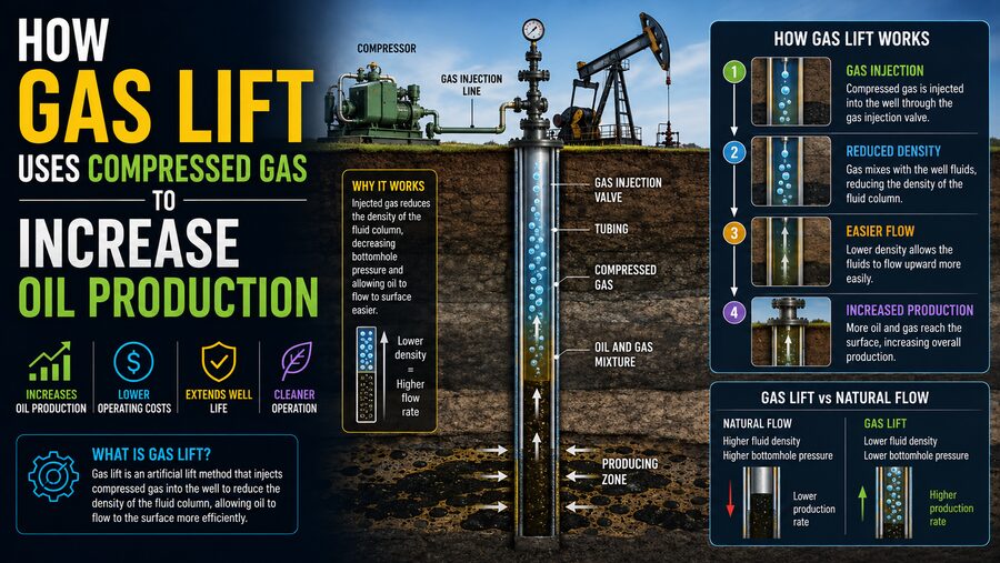
Gas lift is a production technique in which high-pressure gas is injected into the well and mixed with the produced fluids.
The injected gas is usually natural gas, although the exact gas source depends on the production facility.
A typical gas lift system includes:
- a gas compressor,
- surface control equipment,
- injection piping,
- well casing,
- production tubing,
- gas lift valves.
Compressed gas travels from the surface down the annular space between the casing and production tubing.
At a selected depth, the gas passes through a gas lift valve and enters the tubing.
Once inside the tubing, the gas mixes with the oil and other produced fluids.
This mixture becomes less dense than the original liquid column. 🌬️+🛢️
The lighter mixture can then move upward more easily.
📉 The Key Principle: Reducing Fluid Density
The most important principle behind gas lift is density reduction.
Imagine a long vertical tube filled entirely with liquid.
The pressure at the bottom depends heavily on the density and height of the liquid column.
In simplified form:
Hydrostatic pressure ≈ fluid density × gravity × vertical height
If gas bubbles are introduced into the liquid, the average density of the mixture decreases.
Instead of lifting a column made entirely of dense oil and water, reservoir pressure now has to lift a mixture containing significant amounts of low-density gas.
This reduces the pressure required at the bottom of the well to move fluids upward.
As a result, the reservoir can often deliver a higher flow rate. 📈
🧪 A Simple Gas Lift Example
Imagine a well where oil is struggling to reach the surface because the liquid column inside the tubing is too heavy.
Without gas injection:
Dense oil column → high hydrostatic pressure → low production
After gas is injected:
Oil + gas mixture → lower average density → lower hydrostatic pressure → higher production
The injected gas expands as it rises because pressure decreases toward the surface.
That expansion can further help accelerate the fluids upward. ⬆️🌬️
Gas lift therefore assists production through both density reduction and gas expansion.
🏗️ Main Components of a Gas Lift System
A gas lift installation uses both surface and downhole equipment.
⚙️ Gas Compressor
The compressor raises the gas pressure high enough for injection into the well.
The required pressure depends on:
- well depth,
- tubing pressure,
- reservoir conditions,
- injection depth.
Compressors are critical because gas must enter the well at a pressure greater than the local pressure at the injection point.
🛢️ Production Tubing
Production tubing carries oil, gas, and water upward to the surface.
Gas is injected into this tubing through specially designed valves.
🔧 Gas Lift Valves
Gas lift valves control where and when injected gas enters the production tubing.
Several valves may be installed at different depths.
Some are used primarily during well unloading, while a deeper valve may be used for normal production.
🌀 Annulus
The space between the production tubing and casing is called the annulus.
In many gas lift systems, compressed gas travels down the annulus before entering the tubing.
🎛️ Surface Control System
Surface equipment controls injection pressure, gas flow rate, and well performance.
Modern systems may use sensors and automated valves to continuously optimize injection.
🚀 How a Gas-Lifted Well Starts Producing
When a well initially contains a heavy column of liquid, the deepest gas lift valve may not immediately be accessible to the injected gas.
The system therefore often uses several valves installed at different depths.
Compressed gas first enters through an upper valve.
This gas lightens the fluid column and helps push liquid toward the surface.
As the fluid level decreases and pressure conditions change, gas can reach progressively deeper valves.
Eventually, the well reaches its intended operating condition, where gas is injected at a deeper point.
This process is known as unloading the well. 🔄
Once unloading is complete, the well can operate through the designated production valve.
🔁 Continuous Gas Lift
One major type of gas lift is continuous gas lift.
In this system, compressed gas is injected continuously into the production tubing.
The gas mixes with produced liquids at a steady rate, maintaining a lower-density fluid column.
Continuous gas lift is generally suitable for wells with:
- moderate to high production rates,
- sufficient reservoir pressure,
- stable inflow,
- access to a continuous supply of injection gas.
The process operates much like adding bubbles continuously to a liquid stream so that the mixture remains easier to lift.
⏱️ Intermittent Gas Lift
Another method is intermittent gas lift.
Instead of continuously injecting gas, the system injects gas in periodic high-pressure bursts.
The gas pushes accumulated liquid upward in slugs.
Intermittent gas lift can be useful in lower-productivity wells where continuous injection would be inefficient.
A simplified cycle looks like:
Liquid accumulates → gas injected → liquid slug lifted → cycle repeats
This method sacrifices some smoothness of production but can keep marginal wells operating economically.
🌬️ Why More Gas Is Not Always Better
It may seem that injecting more gas should always produce more oil.
That is not the case.
At first, increasing gas injection typically reduces fluid density and increases production.
However, beyond an optimal point, excessive gas can create problems.
Too much gas may:
- increase friction in the tubing,
- reduce liquid-carrying efficiency,
- increase compression costs,
- create unstable flow,
- waste valuable injection gas.
This creates a characteristic gas-lift performance curve.
Production improves as injection increases, reaches an optimum, and may then decline or become economically inefficient.
Finding the correct injection rate is therefore a major part of gas lift optimization. 📊
📈 Gas Lift Optimization
Engineers optimize gas lift systems by balancing oil production against gas use and compressor energy.
They may monitor:
- oil production rate,
- water production,
- gas injection rate,
- tubing pressure,
- casing pressure,
- flowing bottom-hole pressure,
- compressor performance.
Computer models can estimate the best injection depth and gas rate.
Modern facilities may also use automatic control systems that continuously adjust gas distribution among multiple wells.
This is especially important offshore, where one compressor system may supply gas to many wells. 🛢️🌊
🧠 The Role of Pressure
Gas lift depends strongly on pressure relationships.
For gas to enter the production tubing, the pressure of the injection gas must exceed the pressure inside the tubing at the valve depth.
If the compressor cannot provide sufficient pressure, the gas may not reach the intended injection point.
Deeper injection is often beneficial because it lightens a larger portion of the fluid column.
However, deeper injection generally requires higher compressor pressure.
Engineers therefore balance:
- injection depth,
- compressor capability,
- tubing pressure,
- reservoir pressure,
- production objectives.
🌡️ Gas Expansion Helps Lift the Fluid
Compressed gas behaves differently as it moves upward.
Pressure decreases toward the surface.
As pressure falls, gas expands.
This expansion increases gas volume inside the tubing.
The expanding gas can help accelerate the surrounding liquid and continue reducing the average density of the flowing mixture.
The flow inside a gas-lifted well is therefore a complex multiphase flow involving oil, gas, and often water. 🌬️🛢️💧
Engineers use specialized multiphase-flow models to predict pressure and velocity throughout the tubing.
🧱 Why Gas Lift Works Well in Deviated Wells
Some artificial lift systems depend on long mechanical components that move inside the well.
Highly deviated or horizontal wells can make those systems more difficult to operate.
Gas lift, however, has relatively few moving downhole parts.
This makes it especially useful in:
- deviated wells,
- offshore wells,
- deep wells,
- wells producing sand,
- high-temperature environments.
Because the primary lifting action comes from injected gas rather than a downhole motor, the system can be robust under challenging conditions. 🛠️
🌊 Gas Lift in Offshore Oil Production
Gas lift is widely used on offshore platforms.
Offshore wells are often deep, deviated, and expensive to access for maintenance.
A gas lift system can be attractive because much of the active equipment, such as compressors and controls, remains at the surface.
One compressor may distribute gas to several wells through a network of injection lines.
Since natural gas is often already available as part of petroleum production, it can sometimes be recycled and reused for lift.
This makes gas lift particularly compatible with integrated offshore production facilities. 🌊🏭
♻️ Recycling Produced Gas
Gas injected into the well does not disappear.
It returns to the surface mixed with produced oil and reservoir gas.
Surface separators divide the production stream into:
- oil,
- water,
- gas.
Some of the separated gas can be compressed again and returned to the gas lift system.
The cycle becomes:
Produced gas → separator → compressor → gas lift injection → well → separator
This recycling can reduce the need for an external gas supply. ♻️🌬️
However, the gas may need to be treated, dehydrated, or processed before recompression.
🧪 Gas Lift and Multiphase Flow
Flow inside a gas-lifted well is not uniform.
Depending on gas and liquid velocities, several flow patterns may develop.
These can include:
- bubble flow,
- slug flow,
- churn flow,
- annular flow.
Different flow regimes influence pressure drop, stability, and production efficiency.
For example, severe slugging can cause large fluctuations in pressure and production.
Engineers use flow models and real-time measurements to maintain stable operation whenever possible.
⚠️ Challenges of Gas Lift
Gas lift has many advantages, but it also presents engineering challenges.
⚡ Compression Energy
Gas must be compressed to high pressure.
Compressors consume significant energy.
The economic value of additional oil must exceed the cost of compression.
🔧 Valve Reliability
Gas lift valves operate deep underground and can be difficult to repair.
Valve design and installation therefore require careful engineering.
🧱 Corrosion and Scale
Produced fluids may contain corrosive gases, salts, or minerals.
These can damage tubing and valves or restrict flow.
💧 Water Production
As oil wells mature, they may produce increasing amounts of water.
A higher liquid density can increase lifting requirements.
🌀 Flow Instability
Poorly optimized gas injection can create unstable production and pressure fluctuations.
These factors make continuous monitoring important.
✅ Advantages of Gas Lift
Despite its challenges, gas lift offers several important benefits.
It can:
- operate in deep wells,
- handle high production rates,
- tolerate solids better than some pump systems,
- work in deviated wells,
- require relatively little moving equipment downhole,
- adapt to changing production conditions,
- use produced natural gas as lift gas,
- operate in high-temperature environments.
Gas lift systems are also relatively flexible.
Injection rates can be adjusted from the surface as reservoir conditions change.
This makes them suitable for wells whose production characteristics vary over time. ⚙️
🆚 Gas Lift vs. Pumping Systems
Both gas lift and pumps are used to overcome declining reservoir energy, but they work differently.
A pump adds mechanical energy directly to the liquid.
Gas lift modifies the fluid mixture so reservoir pressure can move it upward more easily.
For example:
Pump system:
Mechanical device pushes or pulls liquid upward.
Gas lift:
Compressed gas makes the liquid column lighter.
The best method depends on well depth, flow rate, gas availability, maintenance requirements, fluid composition, and operating economics.
📊 Why Engineers Monitor Flowing Bottom-Hole Pressure
A key goal of gas lift is often to reduce flowing bottom-hole pressure.
This is the pressure inside the well near the producing formation while fluids are flowing.
Lowering this pressure can increase the pressure difference between the reservoir and the wellbore.
That pressure difference helps drive more fluid from the reservoir into the well.
So gas lift can increase production in two connected ways:
- It reduces the pressure needed to lift fluids to the surface.
- This can reduce bottom-hole pressure and encourage greater reservoir inflow.
The interaction between reservoir inflow and tubing performance is central to gas lift design. 📉📈
💰 Economic Optimization Matters
The technically highest production rate is not always the most profitable operating point.
Increasing gas injection may produce more oil, but it also requires more compression power.
Engineers therefore evaluate:
- value of incremental oil,
- electricity or fuel cost,
- compressor limits,
- available gas,
- equipment wear,
- facility constraints.
The goal is often to maximize economic production, not simply maximum physical flow.
For a field containing many gas-lifted wells, allocating limited compression capacity becomes an important optimization problem.
🤖 Digital Monitoring and Smart Gas Lift
Modern oilfields increasingly use digital technologies to optimize gas lift.
Sensors can continuously monitor:
- pressures,
- temperatures,
- gas rates,
- liquid rates,
- valve conditions.
Software can compare real production with predicted performance.
Automated control systems may adjust injection gas remotely.
Advanced systems can even use optimization algorithms to distribute a limited amount of lift gas among many wells so that total field production is maximized. 🤖📊
This turns gas lift from a purely mechanical production technique into a highly data-driven operation.
🌍 From Reservoir Pressure to Surface Production
Gas lift is a powerful example of how engineers can improve oil production without installing a mechanical pump at the bottom of the well.
The method uses compressed gas to reduce the density of the fluid column inside the production tubing. Because the oil-gas mixture is lighter, less pressure is needed to move it upward. 🛢️⬆️
Injected gas also expands as it rises, helping accelerate the fluid toward the surface.
Gas lift can be operated continuously for high-rate wells or intermittently for lower-production wells. It is especially useful in deep, deviated, offshore, and challenging well environments.
Its effectiveness depends on careful control of gas pressure, injection depth, valve behavior, fluid properties, and compression energy.
The core principle is straightforward:
By injecting compressed gas into the production stream, engineers make the fluid column easier to lift, allowing reservoir pressure to deliver more oil to the surface. 🌬️➡️🛢️📈