
A horizontal well has reached a shale or tight-sand interval thousands of metres below the surface. The drill bit may have travelled through rock containing hydrocarbons, yet the well can still produce very little. The missing connection is not necessarily oil or gas in place; it is a practical flow path from the rock to the wellbore.
In a conventional reservoir, connected pore spaces may allow fluids to move toward a well under the reservoir’s natural pressure gradient. In tight formations, the hydrocarbon-bearing rock can have extremely low permeability. Fluid is present, but the pathways through which it could travel are too narrow, poorly connected, or both.
Hydraulic fracturing is an engineering method for creating and supporting conductive pathways in that situation. It does not “make” hydrocarbons. Instead, it changes the effective flow geometry near a well so that hydrocarbons stored in a large volume of tight rock can reach the production system.
Understanding that connection helps students interpret completion diagrams, production trends, pressure behavior, and environmental controls. It also helps working professionals see why reservoir characterization, well design, fluids, pumping, and operations must function as one system. 🔧
🪨 1. The central problem: tight rock does not flow easily
Permeability describes how readily a fluid can move through interconnected pore space. A rock may contain pores and hydrocarbons while still having so little permeability that meaningful flow to an unstimulated well is impractical.
Clay-rich shales, tight sandstones, and some carbonate intervals commonly require stimulation. Their pore throats can be extremely small, and their natural connections may be limited or discontinuous.
The production challenge is therefore a transport problem: increase the area of rock connected to the well and create pathways with much higher conductivity than the original matrix.
🧭 2. Reservoir quality is more than hydrocarbon saturation
Engineers assess whether a formation contains mobile hydrocarbons, but they also evaluate whether those fluids can be delivered. Saturation, pressure, fluid properties, pore structure, mineralogy, stress, and natural fractures all influence the answer.
A productive completion needs a suitable combination of stored fluid, sufficient pressure or energy, and a stimulated rock volume that can communicate with the well. A high hydrocarbon saturation alone does not guarantee a strong well.
- Porosity indicates storage capacity.
- Permeability indicates matrix flow capacity.
- Pressure provides a driving force for production.
- Mechanical properties affect how fractures initiate and grow.
🛢️ 3. The wellbore is the production gateway
The wellbore provides the engineered route from reservoir depth to surface facilities. In modern tight-resource development, the productive interval is often drilled as a long lateral through the target formation.
A horizontal trajectory exposes far more reservoir length than a vertical well through the same thin interval. It also creates a platform for placing multiple fracture treatments along the reservoir contact.
However, a horizontal well is still only a narrow cylinder of access. Hydraulic fracturing expands the connected drainage geometry outward from that cylinder.
📐 4. Why horizontal wells and fractures work together
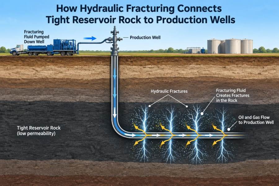
Fractures are placed in separate intervals called stages along the lateral. Each stage is designed to connect a portion of the formation to the wellbore, creating a distributed network of inflow points rather than relying on one small perforated zone.
The lateral provides length; the fracture system provides reach away from that length. Together, they can expose a much larger rock volume to a pressure drawdown.
Stage spacing and cluster placement are not arbitrary. They are selected to balance coverage, fracture interaction, completion cost, operational limits, and geological variability.
💥 5. What hydraulic fracturing actually does
Hydraulic fracturing injects fluid into an isolated section of a well at a rate and pressure high enough to initiate or extend fractures in the surrounding rock. The treatment is designed to create fractures that connect the wellbore with low-permeability reservoir material.
As pumping continues, fluid opens fracture width and propagates the fracture away from the well. Solid particles called proppant are typically carried into the fracture to help preserve a conductive pathway after pumping stops.
The result is not a simple open crack of unlimited extent. It is a complex engineered fracture system shaped by stress, rock layers, natural discontinuities, fluid behavior, and treatment execution.
⚖️ 6. Effective stress controls whether fractures open
Rock at reservoir depth is subjected to stresses from the overlying rock and the surrounding earth. Pore pressure partly supports the rock framework, so engineers often think in terms of effective stress: the stress carried by the solid framework after accounting for pore pressure.
To open a fracture, the fluid pressure near the fracture must overcome the relevant combination of in-situ stress, rock tensile resistance, and pressure losses. Once opened, fracture direction is strongly influenced by the regional stress field.
During production, reservoir pressure declines and effective stress may increase. That can reduce fracture conductivity by squeezing proppant or closing unpropped portions of the fracture.
🧱 7. In-situ stress sets the preferred fracture direction
Hydraulic fractures generally propagate in a plane related to the principal stresses in the formation. In many settings, a vertical fracture grows perpendicular to the minimum principal stress.
Knowing stress orientation helps engineers align horizontal wells and arrange stages. Well azimuth relative to stress can affect fracture geometry, near-wellbore tortuosity, cluster performance, and interference between adjacent fractures.
Stress is not uniform everywhere. Layer changes, faults, depleted zones, and rock-property variation can alter local behavior, so a regional stress map is only the starting point.
🔍 8. Geomechanics explains the rock response
Geomechanics combines rock mechanics, stress analysis, and geological interpretation. It helps predict fracture containment, initiation pressure, possible height growth, and the tendency for fractures to interact with natural planes of weakness.
Elastic properties such as Young’s modulus and Poisson’s ratio contribute useful context, but no single “brittleness” number fully predicts stimulation quality. Mineral composition, bedding, stress contrast, pressure, and pre-existing fractures matter as well.
A geomechanical model is most valuable when it is updated using measurements from drilling, stimulation, and production rather than treated as a fixed pre-job picture.
🌊 9. Fracturing fluid carries energy into the formation
Fracturing fluid transmits hydraulic energy from surface pumps to the fracture. Water-based systems are widely used, although fluid formulation is selected for reservoir compatibility, friction reduction, proppant transport, operational needs, and environmental management.
Additives may be used in controlled amounts for functions such as reducing friction, limiting scale, controlling microbial activity, adjusting viscosity, or improving clay compatibility. Their exact selection depends on the formation and treatment design.
Fluid that returns after stimulation is commonly called flowback. It can include injected water, formation brine, suspended solids, and dissolved constituents from the reservoir.
🏖️ 10. Proppant keeps the fracture conductive
When pumping pressure is removed, the surrounding rock tends to close the fracture. Proppant is placed to hold parts of the fracture open and maintain channels through which hydrocarbons can flow.
Sand is often used because it is available in suitable grades and can perform effectively under many conditions. Higher-strength manufactured materials may be considered where closure stress, crushing resistance, or other design constraints warrant them.
Conductivity depends on more than whether proppant was pumped. Placement, concentration, grain size, embedment, crushing, fines migration, multiphase flow, and stress all affect the pathway over time.
🚪 11. Perforations create entry points from casing to rock
In a cased-and-cemented completion, shaped charges create perforations through the steel casing and cement sheath into the formation. These tunnels are the initial entry points for fracturing fluid and, later, produced fluids.
Perforation design influences how evenly fluid enters selected locations. Shot density, phasing, tunnel orientation, pressure losses, and local rock conditions can all affect initiation behavior.
Perforations are not automatically equal. Some clusters may take more fluid than others, which is one reason engineers use diagnostics and diversion strategies to improve treatment distribution.
🧩 12. Stages divide a long lateral into manageable treatments
A completion stage isolates one part of the horizontal well so pumping energy is focused there. The operator then repeats the process at successive intervals along the lateral.
Common approaches include plug-and-perforate operations and sliding-sleeve systems, though the equipment and sequence vary by field and completion philosophy. The objective is controlled access to multiple intervals.
Staging allows an extended horizontal well to be stimulated section by section. It is one of the practical innovations that makes long laterals productive in tight reservoirs.
🎯 13. Clusters aim to distribute stimulation within a stage
A stage can contain several perforated clusters, each intended to initiate or feed a fracture. The goal is to distribute treatment fluid across the stage rather than concentrating all energy in one preferred location.
In practice, rock and stress variability can cause uneven cluster efficiency. The easiest entry point may accept disproportionate fluid, leaving other intended locations under-stimulated.
Engineers manage this issue with perforation design, limited-entry concepts, rate selection, fluid and proppant schedules, and sometimes diversion. Diagnostics provide evidence of whether the design achieved useful coverage.
📏 14. Fracture geometry has length, height, and width
A fracture treatment is often discussed in terms of half-length, height, and width. Half-length is the distance from the wellbore to one fracture tip; height is vertical extent; width is the opening between fracture faces.
These dimensions affect production differently. Greater reach can contact more rock, excessive height growth can move treatment out of the target interval, and adequate width is needed to transport and place proppant.
| Geometry feature | Why it matters | Key control examples |
|---|---|---|
| Length | Extends reservoir contact away from the well | Volume, rate, leakoff, stress, barriers |
| Height | Determines vertical coverage and containment | Layering, stress contrast, interfaces |
| Width | Supports proppant transport and conductivity | Fluid viscosity, rate, pressure, proppant loading |
🕳️ 15. Natural fractures can help or complicate the design
Many reservoirs contain natural joints, bedding planes, faults, or earlier fractures. A hydraulic fracture may cross these features, open them, be diverted by them, or lose fluid into them depending on stress and geometry.
Natural fracture networks can improve connected surface area, but they can also make fracture growth and fluid placement less predictable. They may contribute to complex pathways that are difficult to describe with a single planar-fracture model.
Faults and other large discontinuities require careful evaluation because they can affect containment, pressure communication, and operational risk.
🧪 16. Treatment design balances competing objectives
A fracture design must deliver enough hydraulic energy to create desired geometry while placing proppant where it can remain useful. Increasing one parameter does not always improve the outcome because the reservoir and completion respond as a coupled system.
For example, a more viscous fluid can improve proppant transport but may introduce different friction, cleanup, compatibility, or cost considerations. Higher pumping rates can change fracture behavior but also increase equipment demands and pressure losses.
- What reservoir interval should be contacted?
- How should stages and clusters be spaced?
- What fluid system is compatible with the formation?
- What proppant schedule can be placed effectively?
- How will success be measured after the treatment?
🖥️ 17. Models guide decisions, but field data tests them
Engineers use fracture models to estimate pressure response, fluid efficiency, fracture geometry, and proppant placement. These models rely on inputs such as stress, rock properties, fluid properties, leakoff behavior, and operational schedule.
Every model simplifies reality. Subsurface heterogeneity, natural fractures, uncertain stress, and changing conditions near the well can produce outcomes different from a pre-job forecast.
Good engineering uses models to structure decisions, then compares predictions with pumping data, diagnostics, and production observations. This feedback loop improves later wells and stages.
📡 18. Diagnostics reveal where the treatment went
Several diagnostic methods can help evaluate stimulation performance. Their usefulness depends on the question being asked, well configuration, data quality, and practical constraints.
Examples of diagnostic evidence
- Pressure analysis can indicate changing fracture behavior, friction, and near-wellbore restrictions.
- Tracer methods can help identify contributions from fluids or intervals.
- Fiber-optic sensing may provide information about activity along a wellbore.
- Microseismic monitoring can indicate rock deformation associated with stimulation, but it does not directly map propped conductivity.
No single measurement gives a complete image of the subsurface fracture system. Interpretation is strongest when multiple data types are considered together.
📉 19. Pressure curves are operational information
Surface treating pressure reflects a combination of friction pressure, hydrostatic effects, perforation losses, near-wellbore behavior, and pressure inside the growing fracture. Changes in the curve can signal that the system is evolving.
A sudden pressure change may have several possible explanations, such as a change in rate, perforation erosion, fracture interaction, diversion response, or equipment behavior. Context and quality control are essential before assigning a cause.
During a treatment, engineers compare real-time measurements with expected operating envelopes. This supports safe execution and helps identify deviations that may require a response.
🔄 20. Flowback begins the transition to production
After pumping, the well is prepared to flow fluids back to surface under controlled conditions. Flowback reduces fluid saturation near the fracture, recovers some injected fluid, and begins establishing hydrocarbon flow through the stimulated pathways.
The early production period can be operationally sensitive. Excessive drawdown may mobilize proppant or fines in some conditions, while overly conservative cleanup can delay effective production; the suitable approach is reservoir- and completion-specific.
Produced fluids are separated, measured, handled, and managed through surface facilities. Water management remains part of the operation long after the pumps have stopped.
🧲 21. Conductivity is the bridge between fracture creation and production
Creating a fracture is not identical to creating a productive fracture. The critical production property is often fracture conductivity: the ability of the fracture pathway to transmit fluid under reservoir conditions.
A long fracture with poor retained conductivity may underperform, while a more effectively propped pathway can deliver stronger flow. Conductivity can decline as stress increases, proppant embeds into softer rock, particles crush, or fluids leave damaging residues.
This is why proppant selection, fluid cleanup, rock strength, closure stress, and drawdown management belong in the same production conversation.
🌡️ 22. Multiphase flow adds real reservoir complexity
Oil, gas, water, and condensate can flow together in and around the fracture system. Their relative movement depends on saturation, pressure, fluid properties, capillary effects, and the geometry of pores and fractures.
Gas can expand as pressure declines, while liquids may create additional resistance to gas flow. In some systems, condensate can accumulate near the wellbore or fracture, changing local mobility.
Consequently, production behavior cannot be inferred from fracture geometry alone. Fluid phase behavior and changing pressure conditions must be considered throughout the life of the well.
📊 23. Production data closes the learning loop
Rates, flowing pressures, fluid ratios, decline behavior, and interference observations offer indirect evidence about the connected reservoir system. They are interpreted alongside completion details and geological context.
A strong initial rate is useful but not the sole measure of completion quality. Sustainable performance, recovery, pressure communication, operating reliability, and economics all matter.
Comparing similar wells requires caution. Differences in landing zone, lateral length, spacing, fluid properties, choke practices, downtime, and facility constraints can obscure the effect of a single design variable.
↔️ 24. Well spacing determines whether fractures compete or complement
Adjacent wells may communicate through fractures, connected natural features, or pressure depletion. Spacing decisions therefore affect both the opportunity to access more rock and the risk of overlapping drainage or fracture interference.
Interactions can occur during stimulation, when a new treatment changes pressures near another well, and during production, when pressure depletion extends through the reservoir. These effects are evaluated with geological, geomechanical, pressure, and production evidence.
The best spacing is not universal. It depends on reservoir quality, stress evolution, fracture dimensions, development timing, and the value placed on recovery versus capital efficiency.
🛡️ 25. Well integrity and environmental controls are integral
Hydraulic fracturing is a high-pressure industrial operation, so safe design and execution depend on multiple barriers and disciplined procedures. Well construction, including casing and cementing, is intended to isolate zones and protect groundwater-bearing formations from the production interval.
Operations also require water sourcing and handling plans, chemical disclosure or reporting where applicable, spill prevention, pressure-control practices, emissions management, waste handling, and monitoring consistent with local requirements and company systems.
Risk management is not separate from engineering quality. Accurate pressure testing, equipment maintenance, competent crews, contingency planning, and clear data records support both safer operations and more reliable outcomes. 🌍
👷 26. The core principle: create a durable flow connection
Hydraulic fracturing connects tight reservoir rock to a production well by creating fractures that increase contact area and by placing proppant to preserve conductive channels after pumping. The wellbore, perforations, stages, fractures, reservoir matrix, and surface system must all work as a connected chain.
The best designs are not defined by a single pumping metric or a simplified picture of a crack in rock. They are built from reservoir understanding, geomechanics, completion engineering, measured execution, responsible operations, and learning from production response.
In tight reservoirs, hydraulic fracturing turns stored hydrocarbons into producible fluids by building and sustaining the flow paths that the original rock cannot provide on its own. 🔧🪨📈