
A fuel pump clicks off. A delivery truck leaves a terminal. A refinery receives another stream of crude oil. Long before any of those visible moments, fluids have traveled through a carefully designed underground system that may extend several kilometres below the surface.
It is easy to picture an oil well as a hollow pipe that simply “sucks” oil from the ground. Real wells work differently. They connect a rock formation containing fluids to controlled equipment at the surface, while managing pressure, water, gas, sand, heat, corrosion, and environmental risk.
For petroleum engineers, this journey explains why reservoir performance and surface operations cannot be treated as separate problems. A decision about perforations, pump settings, or choke size can change what happens throughout the entire production system.
Following one barrel-equivalent of produced fluid from reservoir rock to the wellhead is one of the clearest ways to understand the discipline.
🧭 The Well Is a Flow System, Not a Straw
An oil well is a pressure-connected system made up of the reservoir, the near-wellbore rock, the completion, the tubing, and surface equipment. Fluids move only when there is enough energy to overcome resistance along that route.
The useful question is not simply, “How much oil is underground?” It is: can fluids flow safely and economically from this particular reservoir into this particular well? A large oil volume can still be difficult to produce if permeability is poor, pressure is low, or the fluid is unusually viscous.
🪨 The Reservoir Begins as Pore Space
Oil is usually held within tiny connected spaces between mineral grains in sedimentary rock. Sandstone and carbonate formations are common reservoir rocks because they can contain pore space and pathways for fluid flow.
Porosity describes how much empty space exists in the rock. Permeability describes how readily those spaces connect. A sponge analogy helps: it may hold water, but if its passages are clogged or poorly connected, water will not move easily through it.
🌊 Oil, Water, and Gas Share the Same Rock
Reservoirs rarely contain pure oil alone. Formation water is commonly present, and natural gas may be dissolved in the oil or form a separate gas zone. These fluids occupy the same pore network and compete for pathways.
Gravity tends to arrange fluids by density, with gas above oil and water below, but geology can complicate that pattern. Faults, tilted layers, variable rock quality, and capillary forces all affect where fluids sit and how they move.
📊 Pressure Is the First Source of Energy
Before production begins, reservoir fluids are under pressure created by burial, fluid weight, and geological confinement. When a well is opened in a controlled manner, pressure near the wellbore becomes lower than pressure farther out in the reservoir.
That difference creates a pressure gradient, driving fluids toward the well. It is not suction in the everyday sense; the reservoir pushes fluids toward a lower-pressure flow path.
🔬 Rock Properties Set the Production Ceiling
A highly permeable rock may deliver fluids readily. A tight formation may require a much larger pressure difference or stimulation before useful flow occurs. Thickness, connected volume, fluid viscosity, and natural fractures also influence performance.
Engineers combine core samples, well logs, pressure tests, seismic interpretation, and production history to build a reservoir model. Every model has uncertainty, especially away from existing wells, so forecasts are revised as new data arrive.
🧱 Drilling Creates Access, Not Production
Drilling reaches the target depth and creates a wellbore, but drilling alone does not make a durable producing well. The hole must be protected from unstable formations and isolated from unwanted fluid zones.
Modern wells may be vertical, deviated, or horizontal. A horizontal section can contact more reservoir rock than a vertical well in a thin formation, but it also adds completion and operational complexity.
🛡️ Casing and Cement Build the Well’s Structure
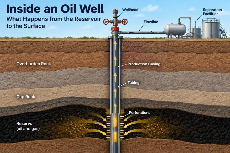
Steel casing is run into the drilled hole in stages. Cement is pumped into the space outside the casing to support the pipe and, crucially, isolate geological layers from one another.
Good zonal isolation helps prevent unwanted water, gas, or pressure from moving behind the casing. Cement quality is therefore a barrier-integrity issue, not merely a construction detail.
- Surface casing protects shallow groundwater zones and stabilizes weak formations.
- Intermediate casing helps manage troublesome pressure or unstable intervals.
- Production casing provides the main conduit across the reservoir section.
🔩 The Completion Turns a Borehole into a Well
A completion is the equipment and configuration that prepares the drilled well for production or injection. It may include tubing, packers, safety valves, perforating hardware, sand-control devices, and downhole monitoring tools.
Completion design depends on reservoir pressure, expected water and gas behavior, sand-production risk, fluid chemistry, well geometry, and planned interventions. There is no universally “best” completion; the right design fits the specific well’s risks and objectives.
🎯 Perforations Open the Reservoir Connection
In a cased-and-cemented completion, shaped charges create small tunnels through the casing, cement, and a short distance into the formation. These tunnels, called perforations, connect reservoir rock to the wellbore.
Perforation placement matters. Opening the wrong interval may bring in excessive water or gas; too few or damaged perforations can restrict flow. Engineers use logs, reservoir interpretation, and sometimes production diagnostics to choose intervals carefully.
🚪 The Near-Wellbore Zone Can Help or Hurt
The rock immediately around the well is called the near-wellbore region. Drilling fluids, fine particles, scale, or clay swelling can reduce permeability there, creating formation damage or skin.
Conversely, natural fractures or effective stimulation can make this region more conductive than the undisturbed formation. Because every produced barrel must pass through this small area, a modest restriction can have an outsized effect on well productivity.
💥 Stimulation Improves the Flow Path
Acidizing can dissolve selected materials or bypass damage in suitable formations. Hydraulic fracturing pumps fluid under controlled conditions to create fractures, then commonly uses proppant to help keep those fractures conductive after pumping stops.
These methods are not interchangeable. Their suitability depends on rock mechanics, mineralogy, natural fractures, water availability, containment, nearby wells, and regulatory requirements. Stimulation can improve access to the reservoir, but it does not eliminate the need for sound well integrity and flow management.
🛢️ Inflow Depends on Drawdown
Drawdown is the difference between average reservoir pressure and flowing pressure near the well. Increasing drawdown often increases production rate, up to limits imposed by the reservoir and completion.
More drawdown is not automatically better. It can accelerate water or gas entry, mobilize sand, encourage scale deposition, damage the formation, or create unstable flow. Production engineering is largely the practice of choosing a productive but sustainable drawdown.
💨 Gas Changes as Pressure Falls
As oil travels toward the well, pressure drops. If pressure falls below the oil’s bubble-point pressure, dissolved gas can come out of solution and form bubbles.
Some gas can help lift fluids by reducing their average density. Too much free gas near the well, however, may reduce oil mobility or interfere with pumps. The result depends on fluid properties and the way gas and oil move through the rock and tubing.
💧 Water Production Is Often Part of the Job
Many wells produce water along with hydrocarbons. It may be original formation water, water moving upward or sideways through the reservoir, or water introduced through injection operations.
A rising water cut can reflect normal reservoir displacement, a high-permeability streak, coning toward the well, a completion problem, or flow behind casing. Diagnosing the cause matters because the right response differs in each case.
🏖️ Sand Control Protects Equipment and Formation
Some weak or unconsolidated formations can release grains when fluids flow. Produced sand can erode valves and chokes, fill the wellbore, damage separators, and create disposal problems.
Gravel packs, frac packs, screens, and rate management are among the approaches used to control sand. Each approach involves trade-offs: aggressive control may restrict flow, while insufficient control can threaten equipment integrity and production continuity.
🧪 Fluid Chemistry Creates Hidden Restrictions
Produced fluids carry dissolved salts, gases, and sometimes solids. Changes in pressure, temperature, or mixing conditions can cause mineral deposits known as scale. Oil and water can also form stable emulsions that are difficult to separate.
Corrosion is another persistent concern, particularly when water, carbon dioxide, hydrogen sulfide, oxygen contamination, or certain bacteria are present. Material selection, chemical treatment, monitoring, and operating discipline work together; no single measure solves every chemistry problem.
⬆️ Tubing Carries Fluids to the Surface
Production tubing is the pipe inside the casing through which fluids normally travel to surface. It allows operators to produce without exposing the casing to the full flow stream and makes certain interventions easier.
A packer often seals the annular space between tubing and casing. This directs production through tubing and helps maintain pressure isolation, although the exact arrangement varies by completion design.
⚖️ The Vertical Lift Problem
Once fluid enters the well, it must travel upward against gravity while losing energy to friction. The total pressure required depends on depth, tubing diameter, flow rate, fluid density, gas fraction, and restrictions.
This is why a well that can deliver fluid from the reservoir may still struggle to reach the surface. Engineers analyze vertical lift performance alongside reservoir inflow to find an operating point where the two systems can work together.
📈 Nodal Analysis Connects the Whole System
Nodal analysis treats selected points in the production system as nodes and compares pressure losses upstream and downstream. A node might be the perforations, pump intake, tubing head, or choke.
It helps answer practical questions: Would a larger tubing size reduce backpressure? Is the choke too restrictive? Would artificial lift improve rate? The method reinforces a central lesson: optimizing one component in isolation can worsen the system elsewhere.
⚙️ Natural Flow Does Not Last Forever
Early in a well’s life, reservoir pressure and gas expansion may be sufficient to lift fluids naturally. As pressure declines or water production rises, the well may no longer have enough energy for reliable flow.
At that point, artificial lift supplies or supports the lifting energy. It does not create oil in the reservoir; it lowers bottomhole flowing pressure or assists the movement of fluid to surface.
🔧 Choosing an Artificial Lift Method
Common artificial-lift systems suit different operating windows. Selection depends on rate, depth, gas handling, solids, deviation, power availability, maintenance strategy, and changing reservoir conditions.
| Method | Basic mechanism | Typical consideration |
|---|---|---|
| Rod pump | Surface-driven downhole reciprocating pump | Widely used; can be affected by gas and solids. |
| ESP | Electric submersible centrifugal pump | Handles high liquid rates; requires suitable power and operating conditions. |
| Gas lift | Injected gas lightens the fluid column | Flexible, but needs gas supply and lift infrastructure. |
| Progressing cavity pump | Rotating positive-displacement pump | Often considered for viscous fluids; elastomer compatibility matters. |
Equipment choice should be revisited as the well changes. A method that performs well at one water cut or gas-liquid ratio may not remain optimal later.
🎛️ The Wellhead Contains and Controls Pressure
At surface, the wellhead supports casing strings and provides pressure-containing connections. The production tree, often called a Christmas tree, includes valves that control and isolate flow.
These are safety-critical components. Their condition, pressure rating, operating procedures, and testing requirements must match the service. A valve is not merely an on-off device when it sits between pressurized fluids and personnel.
🚦 The Choke Regulates the Flow Rate
A choke is a deliberate restriction installed at surface or downhole. By creating a controlled pressure drop, it helps regulate production rate and downstream conditions.
Opening a choke too far can raise rates briefly but may cause unstable flow, excessive drawdown, sand production, equipment erosion, or separator upsets. Choke management should follow measured well behavior rather than a simple “open more, produce more” instinct.
🌀 Multiphase Flow Is Rarely Smooth
In most producing wells, oil, water, and gas travel together. This is called multiphase flow. The phases can form bubbles, slugs, films, or more complex patterns depending on pressure, velocity, pipe angle, and fluid properties.
Slug flow can send alternating liquid surges and gas bursts to surface equipment. It can make separation and measurement harder, create pressure fluctuations, and complicate artificial-lift operation. Flow assurance begins with understanding these changing flow regimes.
🧰 Surface Separation Splits the Stream
At a production facility, a separator uses residence time, gravity, pressure control, and internal devices to divide the incoming stream into gas, oil, and water-rich phases. Heating, chemicals, or electrostatic treatment may be used when emulsions resist separation.
“Oil produced” at the wellhead is therefore not necessarily pipeline-ready oil. It commonly needs further treatment to meet handling, transport, custody-transfer, or refinery requirements.
📏 Measurement Makes Decisions Possible
Operators need to know rates, pressures, temperatures, water fraction, gas volume, and fluid quality. Measurement may involve test separators, multiphase meters, tank gauging, pressure gauges, samples, and automated data systems.
Every method has limitations. Meter performance can be affected by changing fluid properties and flow regimes, while sampling can miss short-lived problems. Good surveillance combines multiple observations and checks whether the measurements make physical sense together.
♻️ Produced Water Needs Responsible Handling
After separation, produced water may be treated, reused where appropriate, discharged only where permitted and compliant, or injected into a suitable disposal or reservoir-management well. The available option depends on water chemistry, infrastructure, regulations, and local conditions.
Water handling can be a major operational constraint even when oil production remains strong. Its volume, salinity, scaling tendency, and compatibility with injection formations must be understood early in field planning.
🧯 Barriers Prevent a Flow Path from Becoming a Hazard
Hydrocarbons and pressurized fluids demand layered protection. Primary barriers may include cement, casing, tubing, packers, and valves; secondary barriers provide backup if the primary barrier fails.
Well integrity management includes pressure testing, inspection, corrosion monitoring, maintenance, clear operating procedures, and documented verification. Barrier failures can develop gradually, so warning signs such as unexpected annulus pressure should be investigated rather than normalized.
🧠 Common Misunderstandings About Production
- “A pump pulls oil out of the rock.” Most pumps primarily lift fluid after it has entered the wellbore; reservoir flow still requires a pressure difference.
- “Higher rate always means better performance.” An excessive rate can reduce long-term value or create safety and reliability problems.
- “Water means the well has failed.” Water production is common; the key question is whether its source and volume are manageable.
- “The well is finished once drilling ends.” Completion quality, surveillance, intervention, and abandonment planning shape the full well life.
🔍 Surveillance Turns Symptoms into Diagnosis
A falling oil rate alone does not identify a cause. It may reflect reservoir pressure depletion, liquid loading, scale, pump wear, water breakthrough, a damaged completion, or a restrictive choke.
Engineers compare trends in pressure, fluid rates, gas-oil ratio, water cut, pump performance, and tests. A disciplined diagnosis prevents expensive interventions based on an appealing but untested explanation.
🛠️ Intervention Restores or Changes the Flow Path
Well interventions range from chemical treatments and wireline logging to scale removal, perforating additional intervals, repairing tubing, recompleting zones, or replacing artificial-lift equipment. The best action depends on identifying the actual restriction or opportunity.
Each intervention carries cost and operational risk. Before acting, teams should define the objective, expected mechanism, success criteria, and evidence that would show the treatment did not work as intended.
🌱 Production Must Include the End of Well Life
A well eventually reaches a point where continued operation is no longer justified or safe. Proper abandonment isolates hydrocarbon-bearing and water-bearing zones using verified barriers, then removes or secures surface equipment according to applicable requirements.
End-of-life planning should begin well before final production. Casing condition, annular pressures, cement quality, future monitoring needs, and site restoration all influence the eventual abandonment scope.
🧩 The Core Takeaway: Manage the Entire Pressure Path
From pore space to separator, oil production is a chain of connected pressure, flow, and containment problems. Reservoir quality determines what can enter the well; completion design controls the connection; tubing and lift move fluids upward; surface equipment regulates, separates, and measures them.
The strongest operational decisions consider the whole system. A well performs reliably when engineers balance production rate with reservoir behavior, equipment limits, fluid chemistry, barrier integrity, and the changing conditions of field life.
An oil well is not a pipe to a hidden pool; it is a managed pathway through rock, steel, fluids, pressure, and time. Understanding that pathway is the foundation of sound petroleum engineering. 🛢️⚙️🌍