
An oil well may flow strongly when it is first completed, driven by the natural pressure in its reservoir. Months or years later, that same well can still contain substantial movable oil while its surface production rate steadily declines.
For a field operator, this is not simply a matter of installing a bigger pump. The fluid arriving at the wellbore may contain oil, water, gas, solids, wax, or corrosive compounds, and the pressure available to lift that mixture changes throughout the life of the well.
Artificial lift is the set of methods used to add energy to well fluids or reduce the pressure opposing their flow. Its purpose is to help a well produce at an efficient, reliable rate after natural reservoir energy is no longer enough.
Choosing and operating the right system requires petroleum engineering, production operations, facilities knowledge, and close attention to well data. A good lift design can extend productive well life; a poor one can create failures, wasted energy, and lost production. ⚙️
🛢️ 1. What Artificial Lift Means
Artificial lift is any engineered method that assists fluids from the reservoir in reaching the surface. It does not create hydrocarbons or replace reservoir energy; it improves the well’s ability to use the pressure and fluid mobility that remain.
Most systems work in one of two ways. They either add pressure or mechanical energy to the produced fluid, or they lower flowing bottomhole pressure so reservoir fluids can enter the well more easily.
📉 2. Why Naturally Flowing Wells Decline
Early in a well’s life, reservoir pressure may be sufficient to overcome hydrostatic pressure in the tubing, friction losses, and surface backpressure. As fluids are withdrawn, that pressure support can diminish.
Water production often rises as a reservoir matures. Because water is typically denser than oil, a taller water-rich fluid column creates more hydrostatic head that the reservoir must overcome.
Gas behavior also matters. Free gas can lighten a fluid column in some conditions, but excessive gas can interfere with pump intake performance and cause unstable flow.
🧭 3. The Pressure Journey From Reservoir to Tank
Production engineers examine pressure along the entire route: reservoir, perforations, near-wellbore region, wellbore, tubing, flowline, separator, and storage system. Every restriction consumes pressure.
A well produces when its reservoir pressure exceeds its flowing bottomhole pressure by enough to move fluids through this system. This pressure difference is called drawdown.
Artificial lift helps manage the wellbore portion of that pressure journey. Surface facilities still impose constraints, so lift equipment cannot be designed in isolation.
🧪 4. Understanding Inflow Performance
Inflow performance describes the relationship between flowing bottomhole pressure and the rate at which a reservoir delivers fluids into a well. Lowering bottomhole pressure usually increases rate, up to limits imposed by the reservoir and completion.
Engineers use an inflow performance relationship, often abbreviated as IPR, to estimate this behavior. The curve is influenced by permeability, fluid properties, pressure, skin, completion condition, and multiphase flow near the wellbore.
A lift system should be selected to work with the well’s inflow capability. Installing capacity far beyond what the reservoir can supply does not produce the intended rate.
📈 5. Matching Inflow With Outflow
Outflow performance describes the pressure required to move a certain fluid rate from the bottomhole to the surface system. Tubing diameter, fluid density, gas fraction, friction, and well depth all affect it.
The operating rate is found where the inflow and outflow behavior are compatible. This is often visualized through nodal analysis, which helps engineers identify whether the main restriction lies in the reservoir, wellbore, tubing, choke, or facilities.
Artificial lift shifts the outflow requirement downward or changes how fluids are transported. The new operating point can yield a higher sustainable production rate. 📊
⚙️ 6. The Main Families of Artificial Lift
Artificial lift systems are commonly grouped by their operating principle. The most widely used options include the following:
- Sucker-rod pumping, where surface equipment drives a downhole reciprocating pump.
- Electric submersible pumping, where a multistage centrifugal pump is run deep in the well.
- Gas lift, where injected gas reduces fluid density and assists flow.
- Progressing cavity pumping, where a helical rotor moves viscous fluid through a stator.
- Hydraulic pumping, where a power fluid transmits energy to a downhole pump.
- Plunger lift, where a free-moving plunger helps unload liquids in gas wells.
No system is universally best. The right choice depends on well conditions, fluid behavior, operational constraints, and field economics.
🏋️ 7. Sucker-Rod Pumps: The Familiar Beam Unit
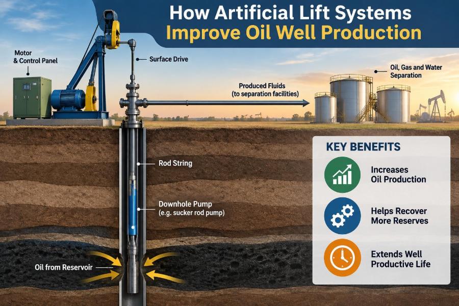
A sucker-rod pumping system uses a surface prime mover and pumping unit to reciprocate a string of rods. The rods operate a positive-displacement pump installed downhole, generally below the dynamic fluid level.
On the upstroke, a traveling valve and standing valve coordinate to lift fluid into the tubing. On the downstroke, the pump barrel refills while the lifted fluid remains supported above the traveling valve.
These systems are visually recognizable by the beam pumping unit, but they can also use low-profile or rotary surface drives. They are especially common in moderate-rate onshore wells.
🔩 8. How Rod Pumping Improves Production
Rod pumping reduces the effective fluid level in the wellbore by removing liquid from the tubing. This decreases flowing bottomhole pressure and allows additional reservoir inflow, provided the pump is properly sized.
The pump displacement depends on plunger area, stroke length, and strokes per minute. Actual production is lower than theoretical displacement when the pump is incompletely filled or when fluid slips through clearances.
Rod pumping offers relatively direct mechanical control, but deeper settings and higher loads increase stress on rods, tubing, gearbox components, and the prime mover.
🌊 9. Electric Submersible Pumps: High-Rate Lifting
An electric submersible pump, or ESP, is a downhole assembly with a multistage centrifugal pump, seal section, motor, power cable, and associated intake equipment. Many stages in series generate the head required to lift fluid from depth.
ESP systems are well suited to wells needing substantial liquid-handling capacity. They are widely applied in high-rate onshore and offshore operations where equipment can be designed around expected production conditions.
At surface, a controller and electrical system provide power and enable operating adjustments. A variable-speed drive can change motor speed, allowing the pump’s operating point to be tuned within its practical range.
🔌 10. Why ESP Operating Range Matters
A centrifugal pump performs best near its intended flow range. Running too far below or above that range can reduce efficiency, create internal recirculation, increase vibration, or accelerate wear.
ESP selection therefore starts with expected liquid rate, required head, fluid properties, well geometry, and pressure conditions. Pump curves are used to relate flow rate, head, power demand, and efficiency.
Gas reaching the pump intake deserves special attention. High free-gas fractions can cause gas interference or gas locking, reducing the pump’s ability to generate pressure. Gas separators and appropriate intake placement can help in suitable wells.
💨 11. Gas Lift: Using Gas as a Lifting Tool
Gas lift injects compressed gas into the production tubing through valves installed in side-pocket mandrels or through other completion arrangements. The gas mixes with produced liquids and lowers the average density of the flowing column.
A lighter column requires less bottomhole pressure to lift fluids to surface. Gas expansion also helps move the mixture upward, particularly in continuous-flow gas lift.
Unlike a downhole pump, gas lift has few moving mechanical parts in the wellbore. However, it depends on a reliable source of injection gas and properly designed compression and distribution facilities.
🫧 12. Continuous and Intermittent Gas Lift
Continuous gas lift injects gas steadily and is generally used when the well has enough productivity to sustain continuous flow. It is often applied across a broad range of production rates.
Intermittent gas lift injects gas in cycles to displace slugs of liquid. It can be useful in lower-productivity wells that cannot support stable continuous production.
Valve depth, injection pressure, tubing size, available gas volume, and well productivity determine whether gas lift can achieve the desired operating condition. Poor allocation of limited injection gas can reduce total field production.
🌀 13. Progressing Cavity Pumps and Viscous Fluids
A progressing cavity pump, or PCP, uses a metal helical rotor turning inside an elastomeric stator. The geometry creates sealed cavities that progress from the intake to the discharge as the rotor turns.
Because it is a positive-displacement system, a PCP can handle viscous oil and certain solids-laden fluids effectively. The relatively gentle pumping action can be useful where emulsions or sand are important considerations.
The rotor is commonly driven from surface through a rod string, although other configurations exist. Stator compatibility with temperature, produced fluids, and chemical environment is a central design concern.
🧱 14. Sand, Solids, and Pump Selection
Produced sand can erode valves, plug narrow passages, wear pump components, and accumulate in the wellbore. Fine solids may also contribute to scale deposits or abrasive wear when carried at high velocity.
Some lift methods tolerate solids better than others, but no method is immune to poor solids management. Completion practices, sand-control strategy, flow rate, and surface handling all influence the risk.
Engineers should distinguish between occasional solids production and persistent sanding. The latter may require a broader production-management response rather than only a different pump.
💧 15. Hydraulic Pumping Systems
Hydraulic lift uses pressurized power fluid from surface to operate a downhole pumping device. Depending on the design, the downhole unit may be a reciprocating pump or a jet pump.
Hydraulic systems can offer flexibility in some deep, deviated, or specialized well applications. Surface power-fluid quality and pressure control are important because the hydraulic circuit is integral to the lift process.
Jet pumps use high-velocity power fluid through a nozzle to create a low-pressure region that entrains produced fluid. They contain no moving parts downhole, although their energy efficiency may be less favorable than some alternatives.
⬆️ 16. Plunger Lift in Gas Wells
Plunger lift is primarily used to remove accumulated liquids from gas-producing wells. A free plunger cycles through the tubing, using gas pressure below it to push a liquid slug toward surface.
By unloading liquids, the system reduces the hydrostatic burden that can restrict gas flow. Surface controllers coordinate shut-in, buildup, arrival, and flow periods based on the well’s behavior.
Plunger lift is not a substitute for a high-volume liquid pump. Its value lies in restoring or sustaining gas-well performance where liquid loading is the main limitation.
🧾 17. Comparing Common Lift Methods
| Method | Primary mechanism | Typical strengths | Important limitations |
|---|---|---|---|
| Sucker-rod pump | Reciprocating positive-displacement pump | Established onshore method; controllable operation | Rod and tubing loads; depth and gas sensitivity |
| ESP | Downhole multistage centrifugal pump | High liquid-rate capability; compact downhole lift | Requires electrical power; sensitive to operating range and gas |
| Gas lift | Gas injection lowers fluid density | Few downhole moving parts; adaptable to deviated wells | Needs compression and injection-gas management |
| PCP | Helical positive-displacement pumping | Useful for viscous fluids and some solids | Stator and elastomer limitations |
| Plunger lift | Pressure-driven liquid unloading | Simple liquid unloading for suitable gas wells | Not intended for high liquid volumes |
The table is a starting point, not a selection rule. Well-specific analysis is always more informative than selecting equipment based on a single strength.
🧠 18. Building a Lift Selection Workflow
A disciplined selection process begins by defining the production problem. Is the well liquid loaded, producing viscous crude, limited by a deep fluid level, affected by gas, or constrained by surface pressure?
Engineers then gather representative data, model feasible options, and check whether the required infrastructure exists. A lift method that works hydraulically may still be impractical if it needs unavailable power, gas compression, workover capability, or produced-water handling.
📋 Useful inputs
- Well depth, deviation, casing, tubing, and completion details.
- Reservoir pressure, productivity, and expected production decline.
- Oil, water, gas, solids, scale, corrosion, and temperature information.
- Surface pressure, flowline constraints, power availability, and operating practices.
🪨 19. Well Geometry Changes the Answer
Vertical wells are not the only design case. In highly deviated and horizontal wells, rod wear, friction, equipment placement, and gas-liquid segregation can strongly affect lift performance.
Rod strings may contact tubing more frequently in deviated sections, increasing wear risk. ESPs and gas lift can be attractive in certain deviated applications, but their installation and operating requirements must still be evaluated.
Completion location matters as well. Pump intake depth, gas-entry zones, perforation interval, and dogleg severity can all influence the quality of fluid delivered to a lift system.
🫗 20. Fluid Properties Drive Equipment Behavior
Oil viscosity affects friction losses, pump fillage, and the power needed to move fluid. High-viscosity fluids can reduce centrifugal-pump performance and may favor positive-displacement approaches in appropriate conditions.
Water cut changes the density and volume of liquid being lifted. Gas-oil ratio, bubble-point behavior, and free-gas volume determine whether gas separation, compression, or special pump configuration is required.
Corrosive gases, scale-forming water, wax, and asphaltenes can shorten run life if not addressed. Chemical treatment and materials selection are therefore part of artificial-lift design, not merely maintenance details.
🛠️ 21. Installation Quality Protects Run Life
Many apparent equipment failures have roots in installation, commissioning, or operating conditions. Correct tubing preparation, cable handling, torque management, pressure testing, and startup procedures can prevent avoidable damage.
For rod-pumped wells, proper rod-string design and alignment help manage loads and wear. For ESPs, electrical integrity, cable protection, motor cooling, and appropriate startup controls are especially important.
A successful installation also establishes baseline data. Initial pressures, rates, power, vibration indicators, and fluid levels make later troubleshooting more reliable.
📡 22. Surveillance Turns Equipment Into a System
Artificial lift should be monitored as a production system rather than treated as a sealed piece of equipment. Rate trends, fluid levels, casing pressure, tubing pressure, electrical measurements, and injection rates can reveal emerging problems.
Rod-pump dynamometer cards can help interpret load and motion behavior. ESP motor current and operating frequency provide useful evidence, while gas-lift wells benefit from monitoring injection rate, injection pressure, and production response.
Remote data systems can speed recognition of abnormal trends, but interpretation remains essential. A changing signal may reflect reservoir decline, a facility upset, a fluid-property shift, or a developing mechanical issue. 📡
🔍 23. Common Failure Modes
Failure modes differ by lift type, but recurring themes include gas interference, solids wear, scale deposition, corrosion, electrical faults, mechanical fatigue, and operation outside the intended range.
⚠️ Examples of diagnostic questions
- Has liquid rate changed because inflow declined, or because the lift system lost efficiency?
- Is free gas entering the pump intake and reducing pump fillage?
- Has a restriction developed in tubing, flowline, valves, or surface equipment?
- Are changing pressures consistent with a leaking valve, worn component, or scale buildup?
Good diagnosis prevents unnecessary workovers. Replacing equipment without identifying the underlying constraint can repeat the same failure pattern.
🧮 24. Optimization Is More Than Maximizing Rate
The highest instantaneous production rate is not always the best operating target. Aggressive drawdown can increase sand production, gas interference, water handling, coning risk, equipment load, or facility constraints.
Optimization seeks a rate that is technically sustainable and economically sensible. It balances production, energy use, maintenance exposure, fluid-handling capacity, reservoir management, and safety.
For example, reducing ESP speed or rod-pump strokes may lower short-term liquid rate but improve pump intake conditions and prolong run life. The best decision depends on the full operating context.
⚡ 25. Energy, Emissions, and Surface Integration
Artificial lift consumes energy directly through motors, engines, compressors, or hydraulic pumps. Its energy demand should be considered alongside the production benefit and the reliability of the available power source.
Gas lift requires compression and gas distribution; ESPs require electrical infrastructure; rod pumping requires a surface drive; hydraulic systems need power-fluid circulation. Each choice affects surface footprint and operating complexity.
Integrating lift design with separation, water disposal, gas handling, and automation can prevent bottlenecks from shifting downstream. Efficient lifting is valuable only if the produced fluids can be safely processed and transported.
🦺 26. Safety and Operational Discipline
Artificial-lift equipment involves stored energy, rotating machinery, electricity, pressure, and potentially hazardous produced fluids. Safe operation depends on procedures, training, isolation practices, inspection, and appropriate protective systems.
Beam pumping units require attention to moving components and suspended loads. Gas-lift facilities require pressure containment and gas-handling controls, while ESP operations require electrical safety throughout installation and troubleshooting.
Production improvement should never be separated from process safety and environmental stewardship. A reliable well is one that can be operated safely over time.
✅ 27. The Core Principle: Match the Lift to the Well
Artificial lift improves oil well production by reducing the wellbore resistance that limits reservoir inflow or by providing the energy needed to transport produced fluids to surface. Its effectiveness comes from matching equipment performance to reservoir inflow, fluid properties, well geometry, and surface constraints.
The engineering task is continuous, not one-time. As reservoir pressure, water cut, gas behavior, and equipment condition change, the lift strategy may need to change with them.
The most effective artificial-lift system is not simply the strongest pump or the lowest-pressure design; it is the system that delivers stable, safe, and sustainable production for that specific well. 🛢️⚙️📈