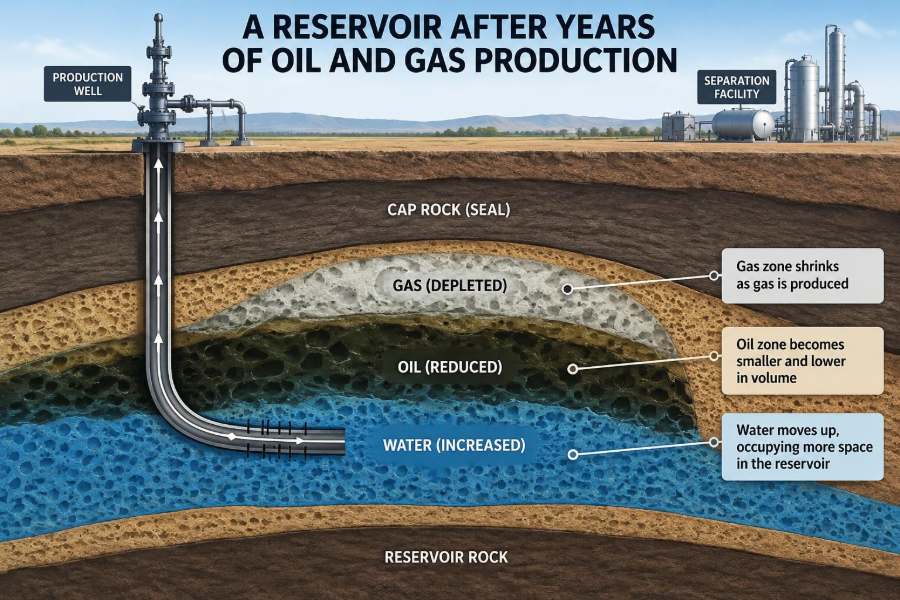

A producing oil or gas field can look calm from the surface. A pump may nod steadily, a wellhead may sit behind a fence, and pipelines may carry fluids away with little visible drama. Underground, however, the reservoir is changing continuously.
Every barrel of oil, cubic metre of gas, and volume of water produced alters pressure, fluid distribution, and sometimes even the shape of the rock framework. These changes determine whether a field continues to perform, becomes difficult to operate, or leaves valuable hydrocarbons behind.
This matters to petroleum engineers because reservoir performance is never just a question of how much oil was originally present. It is a question of how fluids move through a complex rock system over decades, under operating choices that can help or hinder recovery.
For students, this is where reservoir engineering becomes tangible. For working professionals, it is a reminder that production data are not merely numbers on a dashboard: they are clues about a changing subsurface system.
🪨 A Reservoir Is Rock, Not an Underground Lake
The first correction is fundamental: most petroleum reservoirs are not open caverns filled with oil. They are bodies of porous rock, such as sandstone or carbonate, containing tiny connected spaces called pores.
Oil, gas, and water occupy those pores. Their ability to flow depends on permeability, which describes how easily connected pore pathways allow fluids to move. A reservoir can have substantial pore volume but poor permeability, making production slow and technically demanding.
Imagine a water-soaked sponge compressed inside a sealed box. Removing liquid from one part does not mean all liquid can freely rush toward the opening. The sponge structure, fluid properties, and pressure differences control the response.
📦 What the Reservoir Contained at the Start
Before production begins, engineers describe the initial state using pressure, temperature, fluid contacts, rock properties, and fluid saturations. Saturation is the fraction of pore space occupied by a particular fluid.
A simplified conventional reservoir commonly contains:
- oil in part of the pore space,
- water, often at lower structural levels or throughout the reservoir as connate water,
- gas, which may form a gas cap above oil or remain dissolved in the oil.
These fluids are arranged by density, capillary forces, rock heterogeneity, and the geological history of the accumulation. Initial conditions are the baseline against which every later change is interpreted.
🎈 Pressure Is the First Source of Producing Energy
At the beginning of production, a reservoir is typically at a pressure higher than the pressure at the wellbore and surface facilities. That difference supplies the driving force for flow toward the well.
Opening a well lowers pressure near the wellbore. Fluids farther away then move through the rock toward that lower-pressure region. In a healthy, well-connected reservoir, this pressure communication can extend a long distance, though not instantly.
Production therefore removes more than fluid. It removes part of the reservoir’s stored energy. How quickly that energy declines depends on the drive mechanism, production rate, reservoir boundaries, and any injected fluids.
📉 Pressure Depletion Spreads Beyond the Well
The pressure decrease around a producing well is often called a pressure drawdown. With time, the low-pressure zone expands outward. Engineers use pressure measurements and transient tests to estimate how the reservoir responds.
In a homogeneous reservoir, pressure may communicate relatively smoothly. Real reservoirs are rarely homogeneous. Shale layers, faults, tight streaks, natural fractures, and permeability changes can slow, redirect, or compartmentalize pressure movement.
A falling field-average pressure is not automatically a problem. It is an expected consequence of many production strategies. The engineering question is whether pressure is declining in a controlled way that still mobilizes hydrocarbons efficiently.
🔋 Natural Drive Mechanisms Take Over
As pressure changes, different sources of energy can support production. A reservoir may have one dominant drive mechanism or a combination that evolves during field life.
| Drive mechanism | Main source of energy | Typical operational implication |
|---|---|---|
| Solution-gas drive | Gas released from oil as pressure falls | Pressure can decline rapidly; gas handling becomes important |
| Gas-cap drive | Expansion of an existing free-gas zone | Gas-cap management can influence oil recovery |
| Water drive | Water influx from an aquifer | Pressure support may be strong, but water production can rise |
| Rock and fluid expansion | Expansion as pressure declines | Usually contributes modestly but is always present |
No drive mechanism is universally superior. Each changes the production profile, recovery opportunities, facility needs, and risks.
🫧 Dissolved Gas Comes Out of Oil
Many oils contain gas dissolved under reservoir pressure. When pressure falls below the bubble-point pressure, gas begins to come out of solution, much like gas escaping from a carbonated drink after pressure is released.
At first, tiny gas bubbles may remain trapped in pores and contribute little direct flow. As gas saturation increases past a critical level, the bubbles connect and gas can flow more readily toward wells.
This transition matters because flowing gas can consume pressure energy, change oil viscosity, lower oil relative permeability, and raise the gas-oil ratio. Producing gas too aggressively in some settings can reduce the energy available to move oil.
🌊 Water Moves In From Below or the Sides
Many reservoirs communicate with a larger water-bearing formation called an aquifer. As hydrocarbons are withdrawn and reservoir pressure falls, aquifer water may expand or flow into the hydrocarbon-bearing rock.
Water influx can be valuable because it provides pressure support. But it can also push water toward producing wells, eventually increasing water cut: the fraction of produced liquid that is water.
The water front does not necessarily advance as a clean, flat boundary. Layering and permeability contrasts can allow water to race through highly permeable zones while oil remains in tighter zones nearby.
🧭 Fluid Contacts Do Not Stay Still
At initial conditions, engineers may map an oil-water contact or gas-oil contact. During depletion and injection, these contacts can shift. The movement reflects changing pressure gradients, gravity segregation, capillary forces, and production patterns.
In a water-driven reservoir, the oil-water contact may rise locally. In a gas-cap reservoir, gas may move downward or laterally toward production wells. These shifts are often uneven because the rock is not uniform.
Contact movement is one reason a well’s early performance cannot safely be assumed to represent its late-life behavior. A well completed near a contact may encounter unwanted water or gas much sooner than a structurally higher well.
🚦 Relative Permeability Governs Multiphase Flow
When oil, water, and gas share the same pore network, they interfere with one another. Relative permeability describes the effective ability of each fluid phase to flow when other phases are present.
A rock may have high absolute permeability to a single fluid but much lower effective permeability to oil after water saturation rises. Similarly, a growing gas saturation can reduce the pathways available to oil.
This is why “there is still oil in the reservoir” does not mean it can be economically produced. Some oil becomes disconnected, held by capillary forces, or bypassed because another fluid has found easier flow paths.
🧲 Capillary Forces Hold Fluids in Small Pores
Capillary pressure arises from the interaction between fluid interfaces and rock surfaces. In fine pores, it can be strong enough to retain water or oil against a pressure difference that would seem significant at larger scale.
Wettability also matters. A water-wet rock tends to preferentially hold water on mineral surfaces, while an oil-wet system behaves differently. Wettability influences saturation distribution, displacement efficiency, and interpretation of laboratory data.
These pore-scale effects explain why residual oil remains after water has swept through a zone. The water may have displaced mobile oil, yet droplets and films can remain trapped in the complex geometry of the rock.
🧩 Heterogeneity Creates Fast Lanes and Dead Ends
Reservoirs are geologically variable. Sedimentary layers can differ in grain size, cementation, pore throat size, and permeability over short distances. Carbonates may add vugs, fractures, and irregular flow channels.
Higher-permeability intervals behave like fast lanes. They may deliver strong early rates, but they can also allow injected water or gas to bypass lower-permeability zones containing oil. Lower-permeability rock may hold large fluid volumes while contributing little to a well.
Good reservoir management begins with accepting this complexity rather than treating a field as a single uniform tank. Logs, cores, seismic interpretation, pressure data, and production histories each reveal different parts of the picture.
🧱 Barriers Can Divide One Field Into Compartments
Faults and sealing shale beds may restrict flow between parts of a reservoir. Two wells that appear close on a map may not communicate effectively if a barrier lies between them.
Compartmentalization can preserve pressure in one block while another depletes. It may also cause apparently contradictory well behavior: one well sees rapid pressure decline, while another maintains pressure or has a different fluid contact.
The opposite error is also possible. Assuming every fault seals can lead to overly fragmented models. Engineers test communication through pressure behavior, interference observations, tracer information where applicable, and geological evidence.
🛠️ Production Rate Changes the Subsurface Response
A higher production rate increases drawdown near the well. This can raise short-term output, but it may also encourage gas coning, water coning, sand production, or premature breakthrough in sensitive reservoirs.
Rate management is therefore a trade-off rather than a simple instruction to produce as fast as possible. The best rate depends on fluid mobility, completion design, facility capacity, economics, rock strength, and recovery objectives.
A hypothetical well above an active aquifer may produce clean oil at a moderate rate. If its rate is sharply increased, the stronger local pressure gradient can pull water upward toward perforations, raising water cut and reducing oil productivity.
🌀 Coning Pulls Water or Gas Toward Perforations
Coning occurs when water below an oil zone or gas above it is drawn toward a producing well faster than gravity can maintain separation. The fluid interface deforms into a cone-like shape near the well.
Once water or gas breaks through, the undesired phase can dominate flow because it may have favorable mobility or follow an established channel. Reducing rate can sometimes stabilize the situation, but it does not always reverse the pathway.
Completion placement, perforation interval selection, horizontal-well design, and controlled drawdown can reduce coning risk. The right approach is reservoir-specific; simple rules based only on vertical distance are unreliable.
💧 Water Cut Usually Rises With Field Age
As water encroaches naturally or is injected for pressure maintenance, many mature fields produce increasing volumes of water alongside oil. Water handling can become the dominant operational burden even when oil production remains worthwhile.
Produced water must be separated, treated as required, monitored, and often reinjected or disposed of through approved systems. High water rates increase pumping, chemical, corrosion-control, and facility demands.
Rising water cut does not always mean a reservoir is “finished.” It may indicate a local breakthrough, a poorly performing interval, or a field-wide maturity trend. Diagnosis should distinguish these possibilities before choosing a remedy.
🔥 Gas Production Can Become More Complicated
In oil reservoirs, gas-oil ratio may rise as dissolved gas evolves and becomes mobile, or as a gas cap moves toward wells. In gas reservoirs, declining pressure changes gas density, deliverability, and the ability to lift liquids.
Liquid loading is a common late-life concern in gas wells. When gas velocity becomes too low to carry produced water or condensate upward, liquids can accumulate in the wellbore and further restrict gas flow.
Surface constraints matter too. Compressors, separation equipment, pipeline pressure, and gas treatment facilities may become limiting as the produced-fluid mix changes over time.
🧪 Condensate Banking Can Restrict Gas Flow
Gas-condensate reservoirs contain fluids that may drop liquid hydrocarbons when pressure near the wellbore falls below the dew-point pressure. This liquid condensate can accumulate around the well, forming a condensate bank.
The bank reduces gas relative permeability in the near-well region, creating an additional productivity loss. A well may therefore underperform even if substantial gas remains farther from the wellbore.
Possible responses can include pressure maintenance, managing drawdown, stimulation, or fluid-specific operating strategies. Their suitability depends on rock properties, phase behavior, economics, and the ability to maintain pressure at field scale.
🏜️ Near-Wellbore Damage Adds Another Restriction
Not every production decline originates in the reservoir at large scale. The rock immediately around a well can be damaged by drilling fluids, fines migration, scale, wax, asphaltenes, clay swelling, or completion-related effects.
This restriction is often represented by skin, a term that describes additional pressure loss near the wellbore. Positive skin generally indicates impaired flow, while a stimulated well may have reduced flow resistance.
Distinguishing formation damage from reservoir depletion is essential. A declining well may benefit from a targeted cleanup or stimulation, whereas a field-wide pressure decline requires a broader reservoir-management response.
🏖️ Rock Compaction Can Change Pore Space
As reservoir pressure falls, the effective stress acting on the rock framework can increase. Some formations compact measurably, reducing pore volume and sometimes permeability.
Compaction is not always harmful. In certain reservoirs, pore-volume reduction can contribute energy that helps expel fluids. But excessive compaction can reduce productivity, deform wells, damage completions, or contribute to surface subsidence.
Weak, unconsolidated formations require particular attention. Geomechanical models combine rock strength, stress, pressure, and operational conditions to assess compaction and sand-production risk.
🌍 Surface Subsidence Is a Reservoir Management Issue
If significant compaction occurs over a broad area, the land or seafloor above a reservoir may subside. The degree and consequence depend on depth, rock behavior, reservoir extent, and surface setting.
Subsidence can affect well integrity, seabed equipment, drainage patterns, and nearby infrastructure. It is not an inevitable outcome of production, but it is a risk that must be evaluated where pressure depletion and compressible formations coincide.
Pressure maintenance may reduce compaction in some settings, although it introduces its own costs and injection-management requirements. Monitoring is more useful when paired with a clear geomechanical interpretation rather than treated as a stand-alone exercise.
💉 Water Injection Replaces Some Lost Energy
Waterflooding injects water into selected wells to maintain pressure and displace oil toward producers. It is one of the most widely used secondary-recovery approaches because water is generally available, relatively inexpensive to handle compared with some alternatives, and effective in suitable reservoirs.
Success depends on areal sweep and vertical sweep: whether injected water reaches the intended parts of the field across the map and through its layers. Injection into a high-permeability streak may simply short-circuit to a nearby producer.
Injection patterns, rates, water quality, reservoir compatibility, and producer controls all matter. Waterflooding is a managed displacement process, not merely a way to put water underground.
🌬️ Gas Injection Has Different Strengths and Limits
Gas injection can provide pressure support, maintain a gas cap, recycle produced gas, or in some cases improve microscopic displacement of oil. The outcome depends strongly on oil composition, pressure, temperature, and whether injected gas becomes miscible with oil.
Miscible displacement means the injected fluid and oil mix sufficiently that interfacial tension is greatly reduced, helping mobilize oil that water alone may leave behind. Achieving and sustaining suitable conditions is not simple.
Gas has low density and can override oil because of gravity segregation. It may also channel through fractures or high-permeability zones. Mobility control and conformance management are therefore central to gas-injection design.
🧯 Enhanced Recovery Is Not a Universal Next Step
Enhanced oil recovery, often shortened to EOR, includes thermal, chemical, and gas-based methods intended to improve recovery beyond primary depletion and conventional waterflooding. Examples include steam processes for some heavy oils, polymer flooding, and selected gas injection schemes.
These methods can be powerful when matched to the reservoir and fluids. They also bring higher complexity: chemical compatibility, heat losses, injectivity, corrosion, produced-fluid treatment, containment, and economic uncertainty may all matter.
The practical lesson is not that mature fields always need EOR. It is that late-life opportunities should be screened with realistic reservoir characterization and pilot-scale learning where appropriate.
📈 Decline Curves Tell a Story, Not the Whole Story
Production decline analysis is useful for recognizing trends and estimating future performance. A falling rate may reflect depletion, but it can also reflect operational downtime, changing choke settings, increasing water handling, wellbore problems, or facility constraints.
Using decline curves without reservoir context can lead to false confidence. A stable rate, for example, may result from increased drawdown rather than stable reservoir health.
The strongest forecasts integrate production history with pressure data, well interventions, fluid properties, injection performance, and an understanding of changing operating conditions.
🖥️ Reservoir Models Are Decision Tools
A reservoir simulation model represents the field using a grid, rock properties, fluid behavior, wells, and operating controls. It is designed to test how different development or recovery choices may affect pressure, saturation, and production.
Models are valuable because they force assumptions to be explicit. Engineers can compare scenarios such as adding an injector, relocating a producer, changing rates, or shutting off a watered-out interval.
But a model is not the reservoir. Its predictions are limited by data quality, scale, geological uncertainty, and assumptions about features that may not be directly observed. History matching improves confidence but does not eliminate uncertainty.
🧭 Surveillance Reduces Guesswork
Reservoir surveillance means repeatedly measuring the field so decisions reflect current behavior rather than outdated assumptions. Useful observations can include pressures, production rates, water cut, gas-oil ratio, injection volumes, temperature, logs, and well tests.
The value comes from connecting measurements. A rising water cut paired with falling pressure and a nearby injector may suggest a different mechanism than the same water-cut rise with stable pressure and no injection response.
Good surveillance asks focused questions: Are wells communicating? Is injected fluid reaching the target interval? Is a productivity loss local or field-wide? Which uncertainty most affects the next decision?
🔍 Interpreting Data Requires Multiple Lines of Evidence
Single measurements can mislead. A pressure reading may be affected by shut-in duration, gauge quality, wellbore storage, or local flow restrictions. Production allocation can be uncertain in commingled completions, where several layers contribute to one well.
Engineers therefore compare independent evidence. Geological maps may support a fault interpretation; pressure interference may test connectivity; production logs may identify a water-producing interval; fluid samples may reveal changing sources.
This disciplined approach is especially valuable in mature assets, where years of interventions and changing operating conditions can obscure the original reservoir signal.
⚠️ Common Mistakes in Mature Reservoir Management
Several recurring mistakes arise when operational urgency overwhelms reservoir understanding:
- assuming all wells see the same reservoir pressure and fluids,
- raising rates without checking coning, sanding, or breakthrough risk,
- treating higher water cut as a reason to abandon a well without diagnosing the source,
- judging an injection project by total injected volume rather than sweep and response,
- using a historical model unchanged after major new production evidence appears.
None of these errors is solved by data alone. They require a clear workflow that links geology, petrophysics, production engineering, facilities, and reservoir engineering.
🤝 Mature Fields Become More Integrated Over Time
Early development often focuses on locating hydrocarbons and establishing reliable production. As a field matures, the dominant questions become more integrated: where is the remaining mobile oil, what limits each well, where is injected fluid traveling, and which intervention has the best risk-adjusted value?
Reservoir engineers work alongside geoscientists, production engineers, drilling and completions teams, facility specialists, and geomechanics professionals. A technically sound plan can fail if the required well intervention, water capacity, compression, or monitoring cannot be implemented.
Late-life management also involves abandonment planning and integrity stewardship. The reservoir may still contain hydrocarbons, but decisions must account for safety, cost, environmental performance, and long-term well barriers.
🧠 The Core Principle: Production Changes the Reservoir
Years of oil and gas production do not simply empty a container. They create a dynamic sequence of pressure depletion, fluid redistribution, phase changes, changing flow paths, and sometimes rock deformation.
The consequences vary widely. A water influx may support pressure while increasing water handling. Gas liberation may provide drive energy while reducing oil mobility. Injection may improve sweep in one area and bypass oil in another. Each effect must be understood in its geological and operational context.
The most effective reservoir management treats production history as feedback from a living subsurface system, then updates decisions as that system evolves.
A mature reservoir still has a story to tell through its pressure, fluids, rock response, and well behavior. Listening carefully to that story is how engineers protect value, manage risk, and make better decisions from first production to final abandonment. 🛢️🪨📊