
A well can appear healthy on Monday, then deliver far less oil by Friday. The separator has not changed, the crew has not changed, and yet the production trend has fallen sharply enough to trigger calls from operations, reservoir engineering, and maintenance.
A sudden decline is rarely “just a production problem.” It can begin in the reservoir, inside the wellbore, at the artificial-lift system, or downstream of the wellhead. The measured oil rate may be only the visible symptom.
That distinction matters because the wrong response can waste time, damage equipment, or leave recoverable barrels in the ground. Increasing choke size, raising pump speed, or acidizing a well before diagnosing the restriction may make a difficult situation worse.
This guide explains why abrupt production drops happen, how engineers separate the most likely causes, and what a disciplined first investigation looks like.
📉 First, Define What “Sudden” Means
Every oil well declines over time as reservoir pressure and fluid mobility change. That expected decline is usually gradual when viewed over weeks or months. A sudden drop is a rate change occurring faster than the well’s recent operating pattern would predict.
The timescale is a useful clue. A fall over minutes or hours often points toward equipment, controls, flow restriction, or measurement. A fall over days may reflect solids, scale, changing inflow, or liquid loading. A decline developing over months is more likely to include reservoir depletion or a slowly growing damage mechanism.
🧭 Production Rate Is Not the Same as Reservoir Performance
The reported oil rate is the result of a chain: reservoir flow into the well, movement up the tubing, artificial lift, surface handling, and measurement. A restriction anywhere in that chain can lower the number recorded as production.
For example, a well may retain strong reservoir inflow but produce less because a failed electric submersible pump cannot lift the fluids. Conversely, a healthy pump cannot compensate indefinitely if the reservoir no longer delivers enough fluid into the well.
🧪 Start by Checking the Data
Before treating the well, verify that the decline is real. Allocation changes, tank gauging errors, meter faults, separator upsets, and incorrect test conditions can all create an apparent loss.
- Compare well-test oil, water, and gas rates with allocated production.
- Check flowing tubing pressure, casing pressure, choke position, and separator pressure.
- Review whether the test duration and stabilization period were adequate.
- Confirm that the well was not curtailed, shut in, or routed differently.
A meter that under-registers oil does not require a workover. Data validation is not glamorous, but it prevents costly false diagnoses.
🗺️ Use the Timing of the Drop as Evidence
Production history should be read alongside an operations timeline. A drop immediately after a chemical change, power interruption, nearby stimulation job, choke adjustment, or facility outage deserves a different investigation from an unexplained decline.
Engineers commonly ask: what changed just before the rate changed? The answer does not prove causation, but it narrows the list of mechanisms worth testing.
🪨 Reservoir Pressure Depletion Can Reduce Inflow
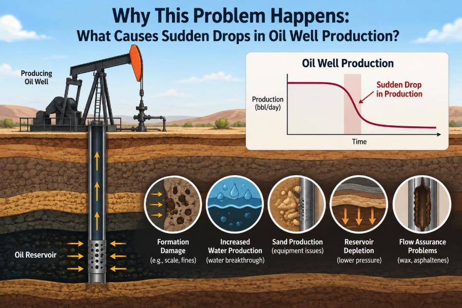
Oil moves toward a well because of a pressure difference between the reservoir and the flowing bottomhole pressure in the well. As reservoir pressure declines, that driving force becomes smaller unless operating conditions change to preserve it.
Depletion is often gradual, but the well response can look abrupt when pressure crosses a threshold. A pump may suddenly become unable to maintain intake pressure, or gas liberation may begin to interfere strongly with liquid flow.
🌊 Water Breakthrough Changes the Well’s Flow Behavior
Water production can rise when a connected aquifer advances, injected water reaches the well, or water enters through a high-permeability streak or fracture. The oil rate may fall because water occupies part of the available flow capacity and changes relative permeability around the well.
Water breakthrough does not always mean the reservoir is “out of oil.” It may indicate that the completion is drawing disproportionately from a watered interval while other zones still contain mobile oil.
🔍 Clues That Support a Water-Related Diagnosis
- A sharp increase in water cut, meaning water as a fraction of total liquid.
- Changes in produced-water salinity or temperature.
- Pressure communication with nearby injectors or offset wells.
- Production logging evidence showing water entry from a specific interval.
🧱 Sand Production Can Choke the Flow Path
Unconsolidated formations may release sand when drawdown is high or the formation has weakened. Sand can accumulate in the wellbore, bridge across perforations, erode equipment, or interfere with downhole pumps.
The initial symptom may be unstable rates rather than a clean decline. Operators may see increased solids at surface, pump wear, erratic pressures, or a rising fluid level above a partially filled wellbore.
🕳️ Formation Fines Can Plug Pore Throats
Fines are tiny mineral particles that can detach and migrate through the rock when fluid chemistry, flow velocity, or stress conditions change. Unlike visible sand, fines migration may damage permeability close to the well without producing obvious solids at surface.
The result is increased near-wellbore resistance: the reservoir still contains fluid, but it has more difficulty entering the completion. This is one form of formation damage.
🧯 Scale Restricts Perforations, Tubing, and Equipment
Scale forms when changes in pressure, temperature, or fluid mixing cause dissolved minerals to precipitate. Common deposits include carbonate and sulfate scales. They may form in perforations, tubing, valves, chokes, pump components, and surface lines.
A scale problem can develop quietly and then become operationally obvious when a narrow passage is sufficiently restricted. Pressure trends, water chemistry, inspection results, and production logs help distinguish scale from reservoir decline.
🕯️ Paraffin and Wax Deposition Reduce Flow Area
Many crude oils contain waxes that can deposit as temperature falls below conditions favorable for keeping them dissolved. Tubing walls, flowlines, and colder surface equipment are common locations.
Wax deposition increases friction and reduces internal diameter. In a severe case, the well may need more pressure to move the same liquid rate than the artificial-lift system can provide. Heating, chemical treatment, mechanical scraping, and operating changes are possible responses, but the best option depends on the fluid and location of deposition.
🧴 Asphaltenes Can Damage the Near-Wellbore Region
Asphaltenes are heavy crude components that can precipitate when pressure or composition changes alter fluid stability. Deposits may form in the reservoir near the well, in perforations, or in the production system.
They are not interchangeable with wax. Their chemistry, deposition conditions, and treatment approaches differ. Assuming every dark deposit is “paraffin” can lead to an ineffective solvent or remediation program.
💥 Completion Damage Raises Skin
Skin is an engineering term describing extra pressure loss near the wellbore. Positive skin means fluid encounters more resistance than expected in an undamaged completion. Drilling-fluid invasion, fines, scale, poor cleanup, and perforation impairment can all contribute.
A well with high skin can show a low production rate despite adequate reservoir pressure. Pressure-transient testing, production logging, and comparison with nearby wells may help establish whether the restriction is near-wellbore rather than deep in the reservoir.
🔫 Perforation Problems Limit Access to the Reservoir
Perforations connect the casing to the producing formation. They can become blocked by debris, scale, fill, or damaged material. They may also be poorly placed relative to the most productive interval.
In a completed well, a sudden loss following intervention may point to perforation or completion issues. In a newly completed well, poor cleanup or incomplete communication with the target zone can prevent expected productivity from appearing in the first place.
🛢️ Gas Liberation Can Reduce Pump Performance
As pressure falls below the oil’s bubble-point pressure, dissolved gas comes out of solution. Some free gas is normal in many producing systems, but excessive gas at a pump intake can reduce the pump’s ability to move liquid.
Gas interference is especially relevant for electric submersible pumps and rod pumps. The effect ranges from reduced efficiency to gas locking, where compressible gas prevents effective pumping action.
⚙️ Electric Submersible Pump Failures Are Often Abrupt
An ESP system includes the pump, motor, cable, seal section, intake equipment, and surface electrical components. Failure in any part can reduce or stop production rapidly.
Warning signals can include changing motor current, unstable intake or discharge pressure, frequent trips, elevated temperature indicators, and a fluid level that rises as the pump loses capacity. However, an ESP running within an expected current range does not by itself prove that the well is producing normally.
🔩 Rod Pump Problems Leave Distinct Clues
For sucker-rod pumping systems, common failures include parted rods, tubing leaks, worn pump components, gas lock, fluid pound, and traveling- or standing-valve leakage. A dynamometer card, which records load and position during a pumping cycle, is a valuable diagnostic tool.
A parted rod can create a dramatic rate loss. Valve leakage may cause a more subtle fall in pump efficiency. The surface unit may continue to move in both cases, which is why visual confirmation that the unit is operating is not enough.
🌪️ Progressive Cavity Pumps Can Lose Efficiency
Progressive cavity pumps use a rotating metal rotor inside an elastomer stator. They are widely used for viscous oils and solids-tolerant service, but elastomer swelling, thermal effects, abrasive wear, torque limitations, and rod-string issues can lower performance.
A sudden torque change or surface-drive alarm is useful evidence, but interpretation requires knowledge of the well’s normal operating envelope. Running faster is not always safe; it can raise loads, worsen wear, or exceed equipment limits.
🧰 Tubing Leaks Waste Lift Energy
A hole or leak in production tubing can allow produced fluid to recirculate into the annulus rather than reach surface efficiently. In some cases, annulus pressure behavior provides an early clue.
The consequences depend on completion design and well-control barriers. Suspected tubing leaks require a controlled integrity assessment, not casual pressure manipulation, because barrier status and environmental risk must be considered.
🚪 A Choke, Valve, or Flowline Restriction May Be the Whole Problem
Not every decline originates downhole. A partially closed choke, malfunctioning control valve, blocked flowline, hydrate formation, or high separator backpressure can reduce a well’s rate substantially.
Think of the production system as a series of pipes. A constriction near the outlet can raise upstream pressure and reduce the pressure drawdown available to pull fluid from the reservoir. Reviewing wellhead and downstream pressures together is therefore essential.
❄️ Hydrates Can Block Gas-Rich Systems
Gas hydrates are ice-like crystalline solids formed when water and light hydrocarbons combine under suitable low-temperature, high-pressure conditions. They can restrict or block valves and flowlines, particularly during cold operations, shut-ins, or depressurization events.
Hydrate management may involve insulation, controlled depressurization, dehydration, or chemical inhibitors. The appropriate method depends on facility design and operating constraints; unsafe warming or pressure changes can create additional hazards.
🏭 High Backpressure Reduces Well Deliverability
Backpressure is the pressure the well must overcome to deliver fluids into the gathering system and separator. If a compressor is down, a separator operates at higher pressure, or a shared line becomes restricted, multiple wells can decline together.
When several nearby wells lose rate at the same time, investigate common facilities early. A field-wide pattern is less likely to be caused by independent downhole failures occurring simultaneously.
🔌 Power, Controls, and Automation Failures Can Mimic Well Failure
Variable-speed drives, motor controllers, pressure transmitters, remote terminal units, and shutdown logic all influence production. A bad sensor can command an unnecessary shutdown or falsely indicate a decline.
Check event logs, setpoints, alarms, and manual-versus-automatic operating mode. The goal is not to blame instrumentation; it is to establish whether the physical well behavior and the control-system record agree.
🧫 Emulsions and Foam Complicate Fluid Handling
Stable oil-water emulsions and foam can disrupt separation, distort level control, increase pressure losses, and make oil-rate measurement less reliable. Chemical changes, fluid composition, and turbulence can all influence their formation.
These problems may look like a reservoir decline if only tank volumes are reviewed. Sampling and process observations can reveal whether the apparent loss is actually a handling or measurement issue.
🔄 Nearby Wells and Injection Can Change Local Conditions
Offset production, water injection, gas injection, and pressure-management changes can alter flow paths around a well. The effect may be beneficial, such as pressure support, or harmful, such as early injected-water arrival.
Correlation alone is not proof. Reservoir surveillance, tracer information where available, pressure data, and geological understanding are needed before attributing a decline to a neighboring operation.
📊 Read Pressures, Rates, and Water Cut Together
No single measurement diagnoses a well. A useful interpretation combines oil rate, total liquid rate, gas rate, water cut, flowing pressures, fluid level or pump intake data, and operating settings.
| Observed pattern | Possible interpretation | Useful next check |
|---|---|---|
| Oil falls; total liquid remains similar; water rises | Water breakthrough or changing zone contribution | Water chemistry and production profile |
| Oil and total liquid fall; fluid level rises | Artificial lift is losing capacity | Pump diagnostics and power history |
| Several wells fall together | Facility backpressure or shared-line restriction | Separator and gathering pressures |
| Rate falls; tubing pressure rises | Downstream restriction or higher backpressure | Choke, flowline, and valve inspection |
| Rate falls after chemical or operational change | Scale, emulsion, damage, or control response | Timeline review and fluid samples |
🧑🔧 A Practical First-Response Workflow
The first response should preserve safety and evidence. Avoid rapid changes that erase diagnostic signals unless an immediate safety or integrity issue requires action.
- Confirm the well is safe, controlled, and within operating limits.
- Validate the production measurement and identify the exact onset of decline.
- Compare current pressures, rates, settings, and alarms with recent stable operation.
- Check facility conditions and shared equipment before assuming a downhole failure.
- Review artificial-lift diagnostics and fluid-level information where applicable.
- Select the least invasive test that can distinguish the leading causes.
🧪 Choose Diagnostics That Answer a Specific Question
A diagnostic is useful when it reduces uncertainty. A fluid sample may help investigate scale tendency or emulsion behavior; a pressure survey may clarify drawdown; a production log can locate fluid entry; and a well test can indicate productivity or changing reservoir behavior.
Tests have limitations. A transient pressure test may be difficult to interpret in a multiphase, unstable well. A production log represents conditions during the survey, not necessarily every operating condition. Results should be integrated rather than treated as a single verdict.
🚫 Common Mistakes During Troubleshooting
The most common error is acting on the first plausible explanation. A declining oil rate is not automatically an ESP failure, scale, water breakthrough, or reservoir depletion.
- Opening the choke without checking downstream constraints and sand risk.
- Increasing pump speed without confirming inflow capacity and pump operating limits.
- Applying chemicals without identifying deposit type or compatibility.
- Interpreting a single noisy test as a permanent trend.
- Ignoring water, gas, pressure, and facility data while focusing only on oil rate.
Good troubleshooting is a process of eliminating alternatives, not simply finding a familiar symptom.
🛠️ Match the Remedy to the Mechanism
A water-entry problem may call for conformance work, selective isolation, recompletion, or a changed drawdown strategy. Scale may require chemical dissolution or mechanical removal. Lift failure may require repair, redesign, or different operating conditions. Facility backpressure may be solved entirely at surface.
Every intervention has trade-offs. A treatment can restore rate but introduce compatibility risks; a higher drawdown can raise production but worsen sanding or water coning; a workover may provide valuable information but adds cost and operational exposure.
🛡️ Prevention Comes From Surveillance, Not Prediction Alone
Sudden drops cannot all be prevented, but their impact can often be reduced through reliable baseline data and routine surveillance. Trending pressures, electrical data, water cut, fluid levels, chemistry, solids, and equipment condition makes abnormal behavior easier to spot early.
Preventive programs should be mechanism-specific. Scale-inhibitor programs need chemical monitoring; wax-prone wells need deposition management; sand-prone completions need drawdown discipline and solids surveillance; artificial-lift systems need operating-envelope monitoring.
🤝 The Best Diagnosis Is Cross-Disciplinary
Reservoir engineers understand inflow and pressure support. Production engineers evaluate lift and well performance. Facilities teams see backpressure and separation behavior. Geoscientists, chemists, integrity specialists, and field operators each contribute evidence that may change the diagnosis.
The operator at the wellhead may notice a vibration, sand pulse, unusual fluid appearance, or control behavior that is absent from a spreadsheet. Combining field observations with structured data is often more effective than relying on either alone.
🎯 The Core Principle: Find the Restriction Before Treating It
Sudden production loss is best understood as a change in one or more parts of a connected flow system. The reservoir may provide less fluid, the near-wellbore region may resist flow, the lift system may move less liquid, or the surface network may impose more backpressure.
The strongest diagnosis explains the rate change, the pressure behavior, the fluid changes, and the timing with the fewest unsupported assumptions. That discipline helps teams choose an intervention that addresses the actual bottleneck rather than the most visible symptom.
A sudden oil-rate decline is a signal to investigate the entire production system, not a reason to guess at the first repair. With sound data, careful comparisons, and mechanism-based action, many production losses can be understood and managed more effectively. 🛢️📊🔧