
A production well can look deceptively simple from the road: a wellhead, a few valves, piping, tanks, and perhaps a pumping unit moving steadily above the ground. But that compact surface footprint represents a long chain of decisions and operations extending thousands of metres below it.
For a drilling or production engineer, the finished well is not merely a hole that reaches hydrocarbons. It is a pressure-containing system, a flow path, a barrier system, and a long-term operating asset built in stages under changing geological conditions.
That distinction matters when production declines, water appears, a valve leaks, or a workover is needed years later. Many apparent “production problems” can be traced back to choices made while the well was being designed and constructed.
Following the construction sequence makes the entire well lifecycle easier to understand. From a geological target to a completed well ready for first production, each stage exists to create a safe, controllable connection between the reservoir and the surface.
🧭 A Well Is a Designed System, Not Just a Borehole
An oil and gas well is engineered to access a subsurface reservoir while isolating formations that should not communicate with one another. It must withstand mechanical loads, corrosive fluids, pressure changes, temperature cycles, and intervention work over its operating life.
The basic architecture includes the wellbore, steel casing strings, cement around those strings, a tubing flow path, downhole completion equipment, and pressure-control equipment at the surface. Each component has a separate role, but their performance is connected.
A useful analogy is a deep, reinforced plumbing system passing through many layers of rock. Unlike household plumbing, however, the system is built while the surrounding formation may contain high pressures, mobile fluids, and unstable rock.
🎯 Starting With the Subsurface Objective
Construction begins long before a rig arrives. Geoscientists and reservoir engineers define the target interval: the rock layer expected to contain movable oil or gas and to deliver it at an economic rate under realistic operating conditions.
Seismic interpretation, offset-well records, well logs, cores, pressure measurements, and production history help reduce uncertainty. They do not eliminate it. A reservoir model is an informed representation of the subsurface, and the actual rock encountered may differ from pre-drill expectations.
The target definition guides key choices such as landing depth, well trajectory, hole size, expected fluid properties, and whether the well will be vertical, directional, or horizontal.
🗺️ Selecting the Surface Location
The surface location must allow the planned trajectory to reach the target while accommodating drilling equipment, future production facilities, access roads, and emergency response needs. In development projects, several wells may be drilled from one pad to reduce surface disturbance.
Location selection also accounts for terrain, existing pipelines, nearby infrastructure, groundwater protection, land access, environmental constraints, and local permitting requirements. These conditions vary substantially by region and jurisdiction.
A directional well provides flexibility: the rig can sit at one location while the bottom of the well reaches a reservoir point laterally displaced from the surface. That flexibility adds trajectory-planning and drilling-complexity requirements.
📐 Designing the Well Before Drilling
The well design translates the subsurface objective into a construction plan. Engineers select casing depths and diameters, drilling-fluid windows, cementing programs, well-control equipment, completion type, and testing plans.
A central design challenge is the gap between pore pressure and fracture pressure. Pore pressure is the fluid pressure in the rock; fracture pressure is the pressure at which the formation may crack and take fluid. Drilling safely requires enough wellbore pressure to prevent influxes without exceeding the formation’s ability to contain it.
This balance is often described as the operational pressure window. Narrow windows can require additional casing strings, more careful fluid management, or specialized drilling approaches.
🏗️ Preparing the Pad and Site Facilities
Before drilling, the location is prepared to support heavy equipment and controlled fluid handling. Typical site work includes grading, constructing access routes, establishing drainage controls, and building a stable pad suitable for the rig and support vehicles.
The exact layout depends on local conditions and operating practices. It may include lined containment areas, tanks, solids-control equipment, generators or electrical supply, lighting, communications, and designated zones for chemicals and waste.
Good site preparation improves more than logistics. It reduces vehicle hazards, makes spill response more manageable, and gives crews space to work around high-pressure equipment without unnecessary congestion.
🚧 The Conductor Establishes the Opening
Construction commonly starts with a large-diameter, shallow conductor. It stabilizes the uppermost ground, provides a controlled starting point for drilling, and helps guide returns from the initial hole section.
The conductor may be driven, drilled, or installed by methods suited to local soil and rock conditions. Its depth is generally shallow compared with the final well, but it is important because loose near-surface material can otherwise wash into the hole.
At this stage, crews also establish the early well-control arrangement and begin building the physical foundation for the next drilling phase.
💧 Protecting Freshwater With Surface Casing
The next major barrier is the surface casing, a steel pipe string run through shallow formations and cemented back toward the surface. Its depth is selected to isolate usable groundwater and provide a secure foundation for pressure-control equipment.
Once the cement has developed sufficient strength, a blowout preventer stack can be installed and pressure-tested. This changes the operation from drilling an open shallow hole to drilling with dedicated equipment capable of closing in and controlling the well.
Surface casing depth is not simply a standard number. It is influenced by local geology, groundwater conditions, anticipated pressures, and applicable regulatory requirements.
🛢️ Drilling Fluid Does More Than Carry Cuttings
Drilling fluid, often called mud, circulates down the drill string and back up the annulus, the space between pipe and hole. It carries rock cuttings to surface, cools and lubricates the bit, stabilizes exposed rock, and helps control formation pressure.
Its density is carefully managed. If it is too light, formation fluid can enter the wellbore. If it is too heavy, it can fracture a weak formation, causing lost circulation and potentially reducing the pressure-control margin.
Fluid properties such as viscosity, gel strength, filtration behavior, and chemical compatibility also matter. Engineers adjust the system as formations, temperatures, and pressure conditions change with depth.
🔩 The Drill String Creates the Hole
The drill string consists of connected pipe rotated from the surface or, in some operations, driven by a downhole motor or turbine. At its lower end, the bottomhole assembly includes the bit, drilling tools, and instruments that measure downhole conditions.
Modern drilling commonly uses measurement-while-drilling tools to provide directional and formation data close to the bit. This allows the team to steer the well and compare actual geology with the pre-drill model.
Drilling is not continuous blind penetration. It is a repeated cycle of drilling, circulating, monitoring, tripping pipe when required, evaluating conditions, and making decisions from incoming data.
🧱 Casing Strings Build Structural Layers
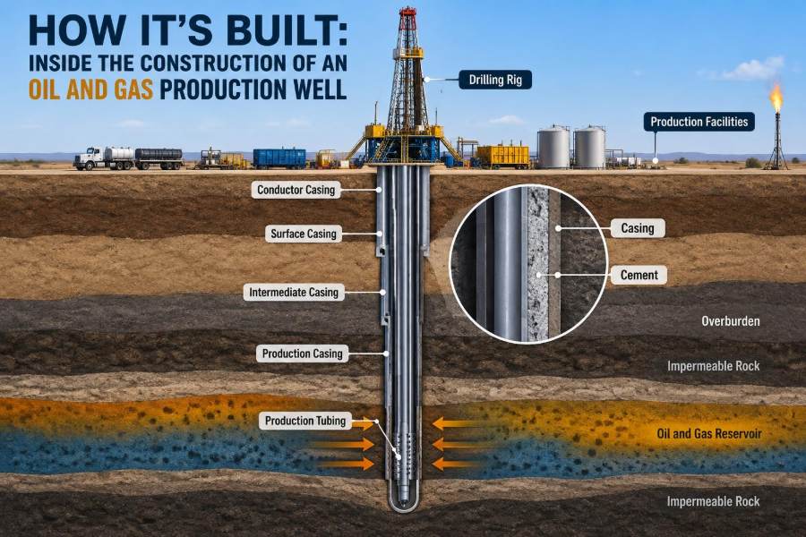
As the well deepens, engineers install progressively smaller casing strings. Each string is run inside the previous hole section, then cemented in place before drilling resumes with a smaller bit.
This telescoping structure allows the well to pass through formations with different pressure and stability characteristics. A common sequence may include conductor, surface casing, intermediate casing, production casing or a liner, though the exact configuration depends on the well.
| String | Primary construction purpose |
|---|---|
| Conductor | Stabilizes the shallow opening and guides early operations |
| Surface casing | Protects shallow formations and supports well-control equipment |
| Intermediate casing | Isolates troublesome zones such as unstable rock or pressure transitions |
| Production casing or liner | Provides long-term integrity around the reservoir interval |
Every added string improves isolation options but reduces the available internal diameter. Well design is therefore a series of practical trade-offs.
🧪 Cement Turns Pipe Into a Barrier System
Cement is pumped down the casing and displaced upward into the annulus around it. When properly placed and set, it supports the pipe, helps prevent fluid movement between formations, and protects casing from certain external environments.
Zonal isolation is the key concept. For example, cement can separate a saline water-bearing formation from a shallower hydrocarbon zone, even though both have been penetrated by the same wellbore.
Cementing quality depends on hole condition, fluid displacement, slurry design, centralization of casing, and placement execution. A cement job is evaluated using pressure tests, returns observations, and, where needed, tools that assess conditions behind pipe.
🧷 Blowout Preventers Manage Well Pressure
A blowout preventer, or BOP, is a set of large valves installed at the top of the well during drilling. It is designed to close around drill pipe, seal an open hole in specific conditions, or control flow through dedicated pressure-control lines.
The BOP is one part of a wider well-control system that includes drilling fluid, pressure monitoring, crew procedures, testing, and trained decision-making. No single device substitutes for disciplined control of the well.
If formation fluids enter the well, the situation is called a kick. Early detection and a planned response are essential because expanding gas or unmanaged influx can rapidly change conditions as it moves upward.
📈 Directional Drilling Reaches More Reservoir
Many wells are intentionally deviated from vertical. Directional drilling uses steering tools and survey measurements to guide the well along a planned three-dimensional path.
In a horizontal well, the trajectory turns through a curved section called the build and then travels laterally within or near the target reservoir. This can expose much more reservoir rock to the well than a vertical penetration.
The benefit is not automatic. Staying in a thin target requires accurate geological interpretation and steering, while long laterals can raise friction, hole-cleaning, casing-running, and completion challenges.
🪨 Logging and Coring Check What the Bit Found
Drilling data indicates how the rock responds to the bit and fluid, but formation evaluation tools provide a more direct picture of the penetrated interval. Wireline logs or logging-while-drilling measurements may indicate lithology, porosity, fluid saturation, and rock properties.
A core is a cylindrical sample of rock recovered from the well. It offers detailed laboratory information that logs alone cannot always provide, although coring costs time and requires careful handling.
No individual log provides a complete answer. Interpretation combines several measurements with cuttings, cores, drilling observations, regional knowledge, and pressure data to decide where and how to complete the well.
⚙️ Reaching Total Depth Is a Decision Point
Total depth is the planned or actual deepest measured point reached by the well. Reaching it does not mean construction is finished; it marks the transition from drilling the final hole section to securing and preparing the productive interval.
The team compares actual depth, trajectory, formation data, pressure behavior, and hole condition against the plan. In some cases, new information supports a change in completion design or identifies an interval that should be isolated rather than produced.
Before proceeding, the final section must be stable enough to run casing or a liner and to perform the planned cementing and completion operations.
🧯 Managing Lost Circulation and Unstable Rock
Two common drilling problems illustrate why construction plans need contingencies. Lost circulation occurs when drilling fluid flows into fractures or highly permeable zones rather than returning fully to surface. This can complicate hole cleaning and pressure management.
Unstable shale, swelling clay, salt movement, or mechanically weak formations can cause the hole to enlarge, collapse, or pack off around the drill string. Fluid chemistry, circulation practices, drilling speed, and casing placement can all influence the response.
There is rarely one universal remedy. The right action depends on the formation mechanism, the pressure window, available materials, and whether continuing poses an unacceptable integrity risk.
🔍 Verifying Barriers Before Moving On
Well construction relies on barriers that are both designed and verified. A barrier may include cement, casing, a tested valve, a plug, or a combination of components that together prevent uncontrolled flow.
Verification can involve pressure testing, negative testing where appropriate, inflow testing, cement evaluation, or mechanical checks of installed equipment. The exact method must fit the barrier being assessed and the operation being performed.
A test result should be interpreted in context. Passing a pressure test demonstrates a condition under defined test parameters; it does not remove the need for ongoing monitoring as pressure, temperature, and loading change during the well’s life.
🔓 Completing the Reservoir Connection
Once production casing is in place and barriers are confirmed, the reservoir must be connected to the inside of the well. In a cased-hole completion, shaped-charge perforating guns create small tunnels through casing, cement, and a short distance into the formation.
Perforation design considers interval selection, shot density, phasing, rock properties, pressure conditions, and the planned stimulation method. The aim is to provide efficient inflow while avoiding unwanted water- or gas-bearing intervals where possible.
Some wells use open-hole completions, in which the reservoir section is left without cemented production casing across the interval. This can suit particular formations but offers different isolation and sand-control options.
🧰 Choosing the Completion Architecture
The completion is the equipment arrangement that enables controlled production or injection. It may be simple, with tubing and a packer, or more complex, with multiple zones, intelligent valves, sand-control screens, and permanent monitoring equipment.
A packer seals the annulus between tubing and casing, directing produced fluids through tubing rather than allowing uncontrolled flow in the casing annulus. This improves containment and lets engineers manage pressure and fluid paths.
Completion design should match reservoir behavior and future intervention needs. A low-cost configuration that cannot isolate water later may be less valuable than a design with greater initial complexity but better operating flexibility.
🏖️ Controlling Formation Sand
Some weak or unconsolidated reservoirs can produce sand grains along with hydrocarbons. Sand production can erode valves and piping, fill the wellbore, damage artificial-lift equipment, and create disposal challenges at surface.
Sand-control choices include screens, gravel packs, frac packs, rate management, or completion strategies that maintain drawdown within a more stable range. Drawdown is the pressure difference that drives fluid from the reservoir into the well.
Not every sand-prone formation requires the same solution. Engineers balance expected production rate, particle size, formation strength, fluid characteristics, and the consequences of a sand-control failure.
💥 Stimulation Can Improve Flow, With Limits
When reservoir permeability is low or near-wellbore damage restricts inflow, stimulation may be used after the well is constructed. Acidizing dissolves selected materials in formations where the chemistry is appropriate, while hydraulic fracturing creates conductive fractures held open with proppant.
These treatments are completion operations, not substitutes for sound drilling and casing design. Their design requires knowledge of stress, rock properties, fluid compatibility, pressure containment, and nearby wells or formations.
Results vary because reservoirs are naturally heterogeneous. A stimulation treatment can improve connectivity, but its performance depends on where created flow paths intersect productive rock and how the reservoir responds over time.
⬆️ Tubing Provides the Managed Flow Path
Production tubing is a smaller steel pipe run inside the casing. It provides the primary route for produced fluids from the reservoir to the wellhead and allows the larger casing annulus to remain available for monitoring or specific operating functions.
Tubing can be retrieved and replaced more readily than production casing, which is valuable when corrosion, scale, wear, or changing production conditions require intervention. Materials and connections are selected for anticipated loads and fluid chemistry.
In a flowing well, reservoir pressure may lift fluids through tubing. As pressure declines or fluid composition changes, artificial lift may be needed to continue moving fluids efficiently.
🔌 Installing Artificial Lift When Natural Energy Falls
Reservoir energy is not always sufficient to deliver fluids to surface at a practical rate. Artificial-lift systems add energy or reduce the effective lifting burden. Examples include rod pumping, electric submersible pumps, gas lift, and progressive cavity pumps.
The appropriate method depends on depth, flow rate, gas fraction, produced solids, fluid viscosity, well geometry, available power or gas, and maintenance strategy. A system that works well in a shallow oil well may perform poorly in a deep, gassy, deviated well.
Artificial lift is often installed after initial production, but it should be considered during construction because completion dimensions, tubing design, and well trajectory affect future options.
🏭 Building the Wellhead and Production Tree
After drilling operations end, the temporary BOP is removed and the permanent wellhead and production tree are installed. The tree is an arrangement of valves, spools, gauges, and connections that controls flow from the well.
These components allow operators to shut in the well, monitor pressures, route production to facilities, and connect intervention equipment. Their pressure ratings and materials must be compatible with expected operating conditions.
The visible tree is only the surface interface of the well. Its reliable operation depends on every downhole barrier and pressure-containing component below it.
🧾 Commissioning Confirms Readiness to Produce
Before routine production begins, equipment is commissioned: valves are checked, pressure-containing connections are tested as required, instrumentation is verified, flow routes are confirmed, and operating procedures are reviewed.
Initial flowback or cleanup may remove completion fluids, solids, or treatment returns before the well enters normal production handling. Produced fluids are commonly separated into oil, gas, water, and solids streams at facilities designed for the field.
Early production data is valuable, but it needs cautious interpretation. Cleanup effects, changing choke settings, and short-term pressure transients can make initial rates unrepresentative of longer-term behavior.
📊 Monitoring Begins on Day One
Construction ends, but integrity management continues. Operators monitor production rates, pressures, temperatures, water cut, gas-oil ratio, annulus pressure, and equipment condition to identify changing reservoir behavior or possible mechanical issues.
A sustained unexpected pressure trend does not identify a single cause by itself. It may reflect reservoir depletion, tubing leakage, packer behavior, scale buildup, changing fluid properties, or an issue at surface. Diagnosis requires evidence from multiple sources.
Routine surveillance turns the well from a static construction project into a managed production system. Records created during drilling and completion are essential when later decisions must be made.
⚠️ Common Construction Mistakes and Their Consequences
Many costly problems are not dramatic failures but small weaknesses that compound over time. Poor hole cleaning can make casing difficult to run; inadequate fluid displacement can compromise cement placement; incomplete documentation can hinder later intervention planning.
- Treating offset data as certainty: nearby wells guide design but do not guarantee identical geology or pressure.
- Rushing barrier verification: unconfirmed isolation can create risks during later operations.
- Ignoring future access: a completion that is difficult to intervene on can raise lifecycle cost.
- Separating drilling and production decisions: choices made for drilling convenience can limit completion or lift performance.
Strong engineering practice connects these decisions rather than optimizing one stage in isolation.
👷 Human Factors Are Part of Well Integrity
Well construction depends on coordinated work by rig crews, drilling engineers, mud engineers, geologists, directional drillers, cementing teams, completion specialists, and service personnel. Clear handovers and shared situational awareness are technical safeguards, not administrative extras.
Procedures matter most when conditions depart from plan. Crews need authority to pause work, report anomalies, verify assumptions, and escalate concerns without treating schedule pressure as a reason to bypass controls.
Automation and real-time data can improve detection and consistency, but they do not remove the need for competent interpretation. A sensor can show a pressure change; people must determine what it means and how to respond.
🌿 Environmental Protection Is Embedded in Design
Environmental protection in well construction includes multiple layers: isolating groundwater, containing fluids at surface, managing emissions, handling wastes appropriately, preventing spills, and designing systems that can be safely monitored and maintained.
Specific practices depend on the location, regulations, formation fluids, and available infrastructure. For example, produced-water handling, gas capture options, and drilling-waste management differ between remote sites and established fields with pipelines and disposal systems.
The most effective approach is preventative. Preventing an uncontrolled release through sound barriers, maintained equipment, and prepared response systems is preferable to relying on cleanup after a problem occurs.
🔄 A Well Is Built for Intervention and Closure Too
Even a productive well may later require a workover to replace tubing, repair artificial lift, isolate a water-producing zone, clean scale, or recomplete another interval. Construction choices affect how practical and safe those interventions will be.
At the end of its useful life, the well must be plugged and abandoned using barriers intended to isolate formations permanently. The detailed requirements vary by jurisdiction and well conditions, but the principle is consistent: remove the pathway for unintended fluid migration.
Thinking about abandonment during design encourages durable records, appropriate materials, accessible wellhead configurations, and a lifecycle perspective rather than a narrow focus on first production.
🧠 The Core Principle: Build Containment and Control at Every Stage
A successful production well is not defined only by reaching hydrocarbons or recording a strong initial rate. It is defined by creating a dependable, verifiable system that can contain pressure, isolate formations, and deliver fluids in a controlled way.
From site selection through cementing, completion, artificial lift, monitoring, and eventual abandonment, the same engineering logic repeats: understand the conditions, select barriers suited to those conditions, test them, and manage change over time.
That is why well construction is such a multidisciplinary discipline. Geology determines the challenge, drilling creates access, completion creates the flow path, and integrity management protects the system throughout its life.
An oil and gas production well is built not simply to reach the reservoir, but to control the connection to it for as long as that connection exists. Seeing the well as a lifecycle barrier system is the foundation for safer, more reliable petroleum engineering decisions. 🛢️🔧🌍