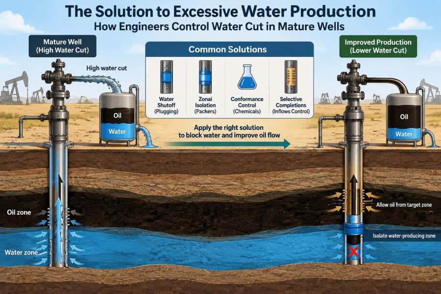

A mature oil well can look healthy from the surface: the pumping unit is moving, fluid is reaching the tanks, and the well is still producing every day. Yet the economics may be deteriorating quietly because most of the produced fluid is water rather than oil.
That change affects far more than a production report. Water must be lifted, separated, treated, monitored, reinjected or disposed of, and managed without harming the reservoir or the environment. A few additional barrels of oil may no longer justify moving a much larger volume of water.
For field operators, excessive water production is a practical puzzle. Where is the water entering the well? Is it flowing through the reservoir, behind pipe, or from an unwanted layer? And can the flow be changed without sacrificing the oil that remains?
Controlling water cut is therefore not one treatment or one tool. It is a diagnosis-led engineering process that combines reservoir understanding, well integrity, production data, and carefully selected intervention methods.
💧 What Water Cut Actually Means
Water cut is the fraction of produced liquid that is water. If a well produces 100 barrels of total liquid per day and 70 barrels are water, its water cut is 70%. The remaining liquid volume is oil, assuming gas is reported separately.
Water cut is not the same as water-oil ratio, although both describe the same operating challenge. Water-oil ratio compares water volume directly with oil volume; water cut expresses water as a share of total liquid. Engineers use both, but must avoid mixing the terms when evaluating trends.
📈 Why Mature Wells Produce More Water
Most oil reservoirs contain water naturally. In many fields, water occupies part of the pore system below the oil zone and provides pressure support as the field is produced. Over time, the movement of this water toward producing wells can become more pronounced.
Waterflooding, in which water is injected to displace oil and maintain reservoir pressure, also contributes to the long-term water-management challenge. It can improve recovery substantially, but injected water will eventually reach production wells through some combination of broad reservoir sweep and faster flow paths.
🧾 Why High Water Cut Changes Field Economics
A barrel of produced water is not simply an extra barrel of fluid. It requires lifting energy, surface handling capacity, chemical treatment in some cases, and an approved route for reinjection or disposal. It can also accelerate corrosion, scaling, and equipment wear.
As water cut rises, oil production may remain technically possible while the net value of the well declines. The operational question becomes: can engineers reduce unwanted water economically, or should they optimize handling and continue producing the remaining oil?
🧭 Start With the Right Diagnostic Question
The useful question is not merely, “How can we shut off water?” It is “What mechanism is bringing water into this well?” A treatment designed for a leaking casing will not solve water coning, and an aggressive reservoir treatment can damage productive oil flow if the diagnosis is wrong.
Water-control work normally begins by separating potential causes into reservoir flow, completion-related flow, and mechanical leakage. This framing prevents teams from treating every high-water well as if it had the same problem.
🪨 Water Moving Through the Reservoir Matrix
In matrix flow, water moves through the small interconnected pores of the rock, much as fluid moves through a sponge. The flow may be relatively broad and distributed across a reservoir interval rather than concentrated in a single channel.
This mechanism often reflects normal displacement behavior as the water-oil contact advances. It may be difficult to stop selectively because the same rock volume can still contain movable oil. The objective may be to improve conformance or manage drawdown, not to block the interval completely.
⚡ Fast Paths: Fractures, Faults, and High-Permeability Streaks
Water does not always travel evenly. Natural fractures, conductive faults, thief zones, and highly permeable layers can provide routes of much lower resistance than the surrounding rock. Water preferentially uses these routes, potentially bypassing oil-bearing portions of the reservoir.
Rapid water breakthrough after injection, a sudden change in produced-water salinity, or a sharp increase in water rate can indicate a fast path. None is conclusive alone, but together with pressure and tracer data they can guide the investigation.
🔺 Understanding Water Coning and Cusping
When a well produces near an oil-water contact, the pressure drawdown around the well can pull water upward toward the perforations. In a vertical well this rising interface is commonly called a water cone. In horizontal wells, a similar local rise may be described as cusping.
Imagine sipping through a straw placed just above the boundary between oil and water. Pull gently and mostly oil enters; pull hard and water can rise toward the straw. Reservoir geometry is more complex, but the analogy captures why production rate matters.
🎯 Completion Placement Can Determine the Outcome
Perforating too close to a water-bearing interval increases the chance of early water entry. So does opening every layer indiscriminately in a vertically heterogeneous reservoir, where some layers hold oil while others are already water-swept.
Selective completion design uses logs, core data where available, pressure information, and reservoir models to decide which intervals should communicate with the well. The best completion is not always the one that exposes the greatest gross thickness; it is the one that accesses profitable hydrocarbons while limiting unwanted fluids.
🔩 Water Entering Behind Casing
Not all water enters through perforations. Poor cement isolation, a microannulus between cement and casing, channels in the cement sheath, or casing leaks can allow water to flow behind pipe and enter the production stream at an unintended depth.
This is a well-integrity problem rather than a reservoir sweep problem. It can connect a water-bearing formation to the production interval, sometimes bypassing barriers that should have isolated the zones. Mechanical integrity must be evaluated before applying reservoir-scale solutions.
🧪 Read Production History Before Running an Intervention
Production history is often the first and most accessible diagnostic tool. Engineers compare oil, water, gas, total liquid rate, flowing pressure, choke settings, artificial-lift changes, workovers, and nearby injector activity over time.
A gradual water-cut rise may fit advancing flood-front behavior. A sudden jump immediately after a mechanical event may suggest completion damage, a newly opened interval, or an integrity issue. The pattern does not prove a mechanism, but it tells the team what to test next.
🧂 Produced-Water Chemistry Offers Clues
Produced-water samples can carry useful fingerprints. Salinity, major ions, dissolved solids, isotopic signatures where justified, and comparison with known formation or injected water may help distinguish likely water sources.
Chemistry must be interpreted carefully. Mixing, sampling errors, scale inhibition chemicals, and changing operational conditions can blur the signal. Water analysis works best as one line of evidence combined with production data and downhole measurements.
📡 Production Logging Locates the Inflow
A production logging tool, or PLT, measures conditions inside the wellbore while the well is flowing or under controlled conditions. Tool strings may include flowmeters, temperature sensors, pressure gauges, fluid-holdup devices, and gamma-ray measurements.
The aim is to identify which intervals contribute oil, water, or gas. A PLT may reveal, for example, that most water enters through a short perforated zone while upper zones still produce oil efficiently. That finding can turn a broad water problem into a targetable completion problem.
🌡️ Temperature and Noise Logs Can Reveal Hidden Flow
Flowing fluids alter the temperature profile of a well. Temperature logs can therefore highlight inflow zones, crossflow, or fluid movement behind casing when interpreted in context. Noise logs can detect sound generated by leaks or turbulent flow through restrictions.
Neither log should be treated as a standalone verdict. Well geometry, shut-in history, flow rate, and tool conditions affect the response. Their value lies in corroborating suspected channels or leak paths before a costly repair is selected.
🧱 Cement Evaluation Tests the Barrier System
Cement-bond and ultrasonic evaluation logs are used to assess the quality and placement of cement behind casing. They can help identify intervals where zonal isolation may be inadequate, although log interpretation is affected by casing condition, cement type, and well configuration.
If evidence points to behind-casing communication, a remedial cement job may be more appropriate than shutting off perforations. Engineers must define the depth, source zone, and flow path as accurately as possible; otherwise, cement can be placed where it does little to stop the water.
🧩 Mechanical Isolation: Plugs, Patches, and Packers
When water enters through a discrete lower interval or a damaged section of tubulars, mechanical isolation can be direct and durable. Common options include bridge plugs, cement plugs, casing patches, straddle packers, and retrievable or permanent isolation assemblies.
The trade-off is selectivity. A plug that stops water may also abandon oil-bearing perforations below it. Before setting a permanent barrier, teams need confidence that the interval has little remaining economic oil or that an alternative completion path can access it later.
🛠️ Selective Recompletion Preserves Better Zones
A well with mixed production from several layers does not always need to be abandoned or fully shut in. Selective recompletion may isolate watered-out intervals, open unswept intervals, or use packers and sliding sleeves to control which zones contribute.
This strategy is especially useful in layered reservoirs with strong contrasts in permeability and water saturation. Its success depends on reliable depth control and a realistic view of communication between layers; an isolated zone can sometimes be bypassed by crossflow elsewhere.
🧴 Chemical Water Shutoff Has a Narrow Target
Polymer gels, resins, and other chemical systems may reduce water flow by entering high-permeability channels and forming a restriction. These treatments are generally considered where water flow is concentrated in a pathway that can be reached without substantially impairing oil flow.
Chemical placement is the central challenge. Fluids tend to enter the easiest path, which can be helpful if that path is truly a water thief zone. But reservoir temperature, brine composition, shear, placement volume, and contact with hydrocarbons all influence treatment behavior.
🧱 Relative Permeability Explains the Selectivity Challenge
Rock can be permeable to more than one fluid at once, but not equally. Relative permeability describes how easily oil and water flow through a rock when both are present. It depends on saturation, pore structure, wettability, and the displacement history.
A water-control treatment must respect this physics. Blocking a pathway that carries only water is desirable; blocking a pathway where oil and water share the same pores can sacrifice valuable oil. Claims of perfectly selective water shutoff should be examined against the specific reservoir conditions.
🧯 Scale, Corrosion, and Solids Are Related Problems
High water volumes can create secondary restrictions. Mixing incompatible waters can precipitate mineral scale, while saline water and dissolved gases can promote corrosion. Fines migration, solids production, and bacterial activity may further affect injectivity, tubing condition, and separation equipment.
These problems can mimic or complicate water-control failures. For example, a falling liquid rate after intervention may be caused by scale deposition rather than successful water reduction. Water chemistry and integrity management belong in the same operating plan.
🚰 Manage Drawdown Before Treating the Reservoir
Sometimes the lowest-risk response is operational. Reducing drawdown by changing choke settings, pump speed, gas lift rate, or pumping schedule can lessen coning or delay water encroachment. This may reduce total liquid rate, but it can improve the oil fraction and lower lifting costs.
The optimum is field-specific. A lower rate can preserve oil productivity, while an overly conservative rate may leave economic production unrealized. Engineers evaluate the rate response against fluid handling limits, artificial-lift performance, and reservoir behavior.
⚙️ Artificial Lift Can Intensify or Ease Water Problems
Artificial-lift systems do not create reservoir water, but their operating conditions can affect how strongly water is drawn toward the well. An oversized electric submersible pump or aggressively operated rod pump can increase drawdown enough to worsen coning in susceptible wells.
Proper pump intake depth, gas handling, pump capacity, and control settings matter. In some wells, optimizing lift delivers more value than a major intervention because it aligns fluid withdrawal with what the reservoir can supply without excessive water influx.
🌊 Injection Management Improves Flood Conformance
In waterflooded fields, water production and injection strategy are linked. If injected water preferentially moves through a thief zone, changing injection allocation, reducing injection into a connected pattern, or applying conformance treatments may improve sweep efficiency.
Changes should be made with reservoir surveillance and pressure management in mind. Cutting injection without understanding pressure support can reduce oil recovery elsewhere. The goal is not simply less produced water, but more productive use of injected water.
🧮 Reservoir Models Help Test Competing Explanations
Material-balance calculations, analytical coning models, sector models, and full-field simulation can test whether an observed water trend is consistent with likely mechanisms. A model is not a crystal ball; its quality depends on input data, assumptions, and calibration against actual performance.
Its strength is comparison. Engineers can estimate the likely consequences of reducing rate, isolating an interval, moving injection, or leaving the well unchanged. This supports better decisions than relying on a single diagnostic observation.
💰 Choose Treatments by Incremental Value, Not Water Cut Alone
A high water cut does not automatically justify a workover, and a lower water cut does not guarantee profit. The economic evaluation should consider expected oil preserved or gained, water-handling savings, intervention cost, probability of technical success, production downtime, and remaining well life.
A modest reduction in water can be valuable where disposal capacity is constrained. Conversely, a technically elegant treatment may be uneconomic if it risks shutting off the last productive oil interval. Decision quality comes from comparing realistic outcomes, not best-case forecasts.
⚠️ Common Water-Control Mistakes
- Treating before diagnosing: applying gel or cement without identifying the entry path can waste money and impair oil production.
- Using water cut as the only indicator: rate, pressure, chemistry, well events, and inflow allocation provide essential context.
- Ignoring behind-pipe flow: perforation isolation cannot repair a leak outside the casing.
- Assuming every water zone is dead: a watered-out interval may still contain recoverable oil under different operating conditions.
- Skipping post-job surveillance: a short-term rate change is not enough to establish durable treatment success.
📝 A Practical Diagnostic-to-Action Workflow
- Verify production allocation, water sampling quality, and measurement reliability.
- Review the well timeline, completion schematic, pressure data, artificial-lift changes, and offset-well behavior.
- Develop several plausible water-source hypotheses rather than selecting the first explanation.
- Acquire targeted logs or tests that can discriminate among those hypotheses.
- Rank interventions by expected value, operational risk, reversibility, and impact on remaining oil.
- Define post-job measurements before the work begins, then compare actual results with the predicted response.
This workflow may seem deliberate, but it often avoids the far greater cost of an irreversible intervention based on incomplete evidence.
📊 How to Judge Whether a Treatment Worked
Success is more than an immediate fall in water rate. Engineers track oil rate, water rate, total liquid rate, water cut, flowing pressure, pump performance, and changes in nearby wells where reservoir communication is possible.
A treatment may lower water rate simply because it restricts all flow. A better result is one that reduces unwanted water while retaining, restoring, or economically protecting oil production. The duration of the response matters as much as the first few days.
🏭 Surface Facilities Set Real Constraints
Water control is sometimes driven by surface bottlenecks rather than the subsurface alone. Separators, hydrocyclones, produced-water treatment units, injection pumps, pipelines, and disposal wells all have operating limits. One high-water well can consume capacity needed by better oil producers.
Field prioritization should therefore account for the entire production system. A water-control candidate may be valuable because it frees treatment capacity, even if its own oil-rate increase is modest.
🌱 Environmental and Safety Responsibilities
Produced water can contain salts, hydrocarbons, solids, treatment chemicals, and naturally occurring constituents that require controlled handling. Storage, transport, reinjection, discharge where permitted, and disposal must follow applicable operating procedures and regulations.
Well interventions also bring pressure-control, chemical-handling, and lifting risks. A technically sound water-control plan includes barrier verification, contingency procedures, waste management, and competent execution—not only a reservoir forecast.
🤝 Water Control Is a Cross-Discipline Decision
Reservoir engineers assess fluid movement and recovery impact. Production engineers evaluate well performance and artificial lift. Petrophysicists interpret logs, completions specialists design isolation, chemists assess treatment compatibility, and operations teams understand what can be executed safely.
The strongest decisions emerge when these perspectives meet early. A reservoir mechanism may be correct but impractical to treat in a particular well; an operationally simple fix may have unacceptable recovery consequences without reservoir input.
🔮 Designing New Wells With Future Water in Mind
Many water problems cannot be eliminated, but their consequences can be reduced during initial well design. Thoughtful trajectory placement, selective completions, zonal isolation, monitoring capability, corrosion allowance, and access for future intervention all improve flexibility.
For example, completion hardware that permits selective shutoff may cost more initially but can avoid a major workover later. The right choice depends on uncertainty, reservoir complexity, expected water movement, and the value of retained options.
🧠 The Core Principle: Match the Remedy to the Mechanism
Excessive water production is not a single failure mode. It can result from normal reservoir displacement, coning, high-permeability channels, fractured flow, poor zonal isolation, casing damage, or a combination of mechanisms. Each calls for a different response.
The enduring lesson is simple: collect evidence, identify the most likely flow path, estimate the consequences of intervention, and protect oil productivity while managing water safely. Water cut is the symptom; the flow mechanism is the engineering problem to solve.
Effective water control comes from matching a selective, economically justified action to a well-understood source of water—not from applying the same fix to every mature well. 🛢️💧🔧