
A subsea well can produce valuable hydrocarbons smoothly at the reservoir, only for the fluid to become a problem on its way to the facility. As pressure falls and temperature changes, the same stream that was easy to move can deposit solids, form crystals, or create mineral layers inside the pipeline.
The operational symptoms may appear gradually: rising pressure drop, lower throughput, unstable separator conditions, or repeated pigging problems. In a severe event, a restriction can interrupt production and require a complex intervention.
This is the practical purpose of flow assurance: keeping produced fluids transportable from the reservoir to processing and export. It combines thermodynamics, fluid mechanics, chemistry, equipment design, monitoring, and operating discipline.
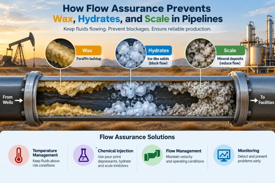
Wax, hydrates, and scale are often discussed together because all can restrict flow. Yet they form for different reasons, respond to different controls, and must be diagnosed carefully before treatment begins. 🌡️
🛢️ 1. What flow assurance means
Flow assurance is the engineering discipline concerned with reliable, safe, and economical movement of oil, gas, water, and solids through wells, flowlines, risers, pipelines, and process equipment.
Its scope includes more than deposits. Engineers evaluate pressure and temperature profiles, multiphase behavior, liquid holdup, slugging, corrosion interactions, restart conditions, chemical delivery, and operability over the asset life.
The key question is simple: will the produced stream remain manageable under every expected operating condition?
🌊 2. Why a pipeline is a changing environment
A pipeline is not just a passive tube. Fluid composition, pressure, temperature, velocity, and phase distribution can change continuously from inlet to outlet.
In a long subsea line, heat transfers to cold seawater while pressure declines because of friction and elevation. In a topside line, cooling may occur during shutdown, while a pressure-control valve can cause a rapid pressure change.
These changes can move the fluid across conditions where wax precipitates, hydrates become stable, or minerals leave the water phase.
🧪 3. The three deposit threats are fundamentally different
| Threat | What forms | Typical driving conditions | Main consequence |
|---|---|---|---|
| Wax | Paraffinic hydrocarbon crystals and deposits | Cooling below wax appearance behavior | Reduced bore and higher pressure drop |
| Hydrates | Ice-like water cages containing small gas molecules | Free water, hydrate-stable pressure and temperature, gas | Rapid plugging risk |
| Scale | Inorganic mineral solids | Water mixing, pressure or temperature change, incompatible ions | Restrictions and equipment fouling |
All three may be called “solids,” but their chemistry and mitigation are distinct. A wax solvent is not a hydrate inhibitor, and a scale inhibitor does not prevent wax crystallization.
🕯️ 4. How wax begins to appear
Crude oil contains many hydrocarbon molecules, including heavier straight-chain components commonly called paraffins. At sufficiently low temperature, some of these components begin to form solid crystals.
The wax appearance temperature, often abbreviated WAT, describes the onset of detectable wax crystallization for a particular fluid under specified conditions. It is not a universal fixed number for every crude, and it can depend on pressure, composition, and the measurement method.
Wax crystals alone are not always harmful. The transport problem develops when crystals grow, interact, attach to the wall, and build a deposit.
❄️ 5. Why cooling promotes wax deposition
As hot produced oil flows through a colder pipe, a thermal gradient develops between the bulk fluid and the wall. Wax molecules can diffuse toward the colder wall, where crystallization and deposition are more likely.
Over time, the deposit acts as an insulating layer. That insulation can slow heat loss but also narrows the flow area and increases frictional pressure loss.
Deposition depends on much more than bulk temperature. Flow regime, shear stress, water cut, crude composition, surface condition, and shutdown history can all matter.
🧱 6. How wax harms operations
Wax deposits reduce the effective internal diameter of a line. For a fixed flow rate, velocity through the remaining open area rises, and pressure drop can increase substantially.
Deposits may also make pigging difficult, interfere with valves and instrumentation, and create an elevated restart risk after a cold shutdown. If a large quantity of wax is remobilized suddenly, downstream separators can receive an undesirable surge of solids and viscous material.
🌡️ 7. Keeping fluids above wax-risk conditions
Thermal management is a direct preventive strategy. Insulated flowlines, pipe-in-pipe systems, buried lines, active heating, and heat tracing can reduce cooling and extend the time before fluids enter a wax-risk range.
The design target is usually not “keep every point permanently above WAT” in every case. Instead, engineers evaluate the expected temperature profile, deposition tendency, operating envelope, and economics to select an appropriate strategy.
- Passive insulation reduces heat loss without external power.
- Active heating supplies heat where long tiebacks or cold surroundings demand it.
- Operational temperature control limits unnecessary cooling during normal operation and shutdown.
🧴 8. Chemical approaches to wax control
Wax control chemicals may modify crystal size, crystal shape, or the way crystals interact. Common categories include wax inhibitors, pour-point depressants, and dispersants, although their functions can overlap depending on formulation and crude behavior.
Performance must be validated with representative fluid and relevant conditions. A chemical that improves low-temperature handling in a laboratory bottle test may not automatically prevent wall deposition in a flowing multiphase pipeline.
Injection location, dosage, mixing, and uninterrupted delivery are as important as selecting the chemical itself.
🐖 9. Pigging removes or manages wax
A pig is a device sent through a pipeline to displace liquids, sweep deposits, separate batches, inspect the line, or perform other tasks. Cleaning pigs can help control wax accumulation before deposits become operationally significant.
Pigging requires a system designed to launch, receive, and safely manage pigs and displaced material. The operating team also needs to understand whether a pig could push a large wax inventory into sensitive downstream equipment.
Routine pigging is often part of a broader wax-management plan, not a substitute for understanding why deposition is occurring.
🧊 10. What gas hydrates are
Gas hydrates are crystalline solids in which water molecules form cage-like structures around small guest molecules, commonly including methane and other light hydrocarbons. They resemble ice in appearance but are chemically different from ordinary ice.
Hydrates require free water, suitable pressure and temperature, and hydrate-forming gas components. They are most often a concern in wet-gas, gas-condensate, and multiphase systems.
Because they can agglomerate and plug a line quickly, hydrates are a major flow-assurance hazard.
📉 11. Why pressure and temperature matter for hydrates
Hydrates are favored at relatively high pressures and low temperatures compared with many surface operating conditions. Deepwater flowlines are especially challenging because cold seawater removes heat while the pipeline may still operate at high pressure.
A pressure reduction can have competing effects. It may shift hydrate stability, but it can also cause gas expansion and cooling through pressure-related thermal effects, potentially bringing the fluid into a more hazardous condition.
For this reason, hydrate assessment uses pressure-temperature behavior together with actual fluid composition and water availability.
💧 12. Free water is the critical hydrate ingredient
Water vapor in dry gas does not present the same immediate plugging mechanism as a separate liquid-water phase. Hydrate formation becomes much more concerning when free water is present as droplets, films, or a continuous water phase.
Condensation, produced water, incomplete dehydration, and water held in low points can all supply the water needed for hydrate growth. Understanding where water resides in the system is therefore as important as knowing the overall water content.
⚠️ 13. Why hydrate plugs are difficult
A hydrate plug can behave as a solid blockage, but its location and internal structure may be uncertain. Pressure can remain trapped on either side, and an incorrect depressurization or restart action can create serious safety and mechanical risks.
Hydrate response procedures therefore emphasize verification, controlled isolation, pressure management, and deliberate remediation. A suspected plug is not simply a maintenance inconvenience; it is an abnormal operating condition that needs disciplined decision-making.
🧪 14. Thermodynamic hydrate inhibitors
Thermodynamic hydrate inhibitors, commonly methanol or monoethylene glycol, change the conditions at which hydrates are stable. In effect, they shift the hydrate-stability boundary so that the operating pressure and temperature are less favorable for hydrate formation.
These chemicals can be effective, but required quantities may be substantial in water-rich systems. Recovery, regeneration, storage, injection reliability, and downstream process impacts must be considered in the design.
Methanol and glycol serve different operational roles, so selection is based on the system and facility configuration rather than a generic preference.
🧬 15. Low-dosage hydrate inhibitors
Low-dosage hydrate inhibitors, or LDHIs, are used at lower concentrations than thermodynamic inhibitors but do not simply shift equilibrium in the same way. They are generally grouped into kinetic hydrate inhibitors and anti-agglomerants.
Kinetic inhibitors delay hydrate nucleation or early growth for a limited time. Anti-agglomerants aim to keep hydrate particles from sticking together into a plug, often by promoting transportable slurry behavior in suitable liquid systems.
LDHI application depends strongly on fluid composition, water cut, subcooling, residence time, and operating conditions. Qualification testing is essential.
🔒 16. Hydrate prevention during shutdown and restart
Normal flowing conditions can be safer than a shutdown because warm production fluid continues to supply heat and high velocity limits settling. Once flow stops, the line cools toward its surroundings and liquids redistribute.
Engineers calculate a cooldown time: the estimated period before conditions in the system reach the hydrate-risk region after shutdown. This helps define how quickly production should restart or when a preservation action, such as inhibitor injection or depressurization, is required.
Restart plans must account for the coldest sections, especially low points and remote subsea lines.
🪨 17. What scale is in production systems
Scale is an inorganic mineral deposit formed when dissolved ions in water become supersaturated and precipitate as solids. Common oilfield scales can involve calcium, barium, strontium, carbonate, sulfate, iron-containing compounds, or other mineral species.
Unlike wax, scale does not originate from hydrocarbon crystallization. Unlike hydrates, it is not a water-and-gas cage structure. It is a mineral precipitation problem controlled by water chemistry and changing conditions.
🔀 18. How incompatible waters create scale
A classic scale scenario occurs when two waters with different dissolved-ion compositions mix. For example, one water may contain abundant cations while another contains sulfate; mixing can create supersaturation for a sulfate mineral.
This can happen when injected seawater enters a reservoir, when formation water reaches the wellbore, or when fluids combine in surface facilities. The exact risk depends on composition, mixing ratio, temperature, pressure, and chemical equilibria.
Compatibility studies are used to identify these risks before waterflooding or production changes are implemented.
⬇️ 19. Pressure and temperature can trigger scale
Scale can form even without mixing two distinct waters. Pressure reduction may release dissolved carbon dioxide from water, change acidity, and alter carbonate equilibria, increasing the tendency for carbonate scale to precipitate.
Temperature changes can also affect solubility and reaction rates. As a result, scale may develop near perforations, in tubing, across chokes, in valves, or in heat-transfer equipment where the local environment changes sharply.
🧷 20. Why scale damages wells and facilities
Scale can reduce productivity in the reservoir near-wellbore region, block perforations, restrict tubing, and foul pumps and safety valves. In pipelines and facilities, it can impair flow, reduce heat-transfer efficiency, and obstruct small-bore equipment.
Some scales are difficult to remove mechanically or chemically. The best solution is often prevention before deposits become thick, inaccessible, or integrated with corrosion products.
🛡️ 21. Scale inhibitors prevent crystal growth
Scale inhibitors are chemicals designed to interfere with nucleation, crystal growth, or crystal agglomeration at very low concentrations relative to the dissolved salts. They do not necessarily remove the ions from the water; they help keep the system manageable despite supersaturation.
Inhibitors may be injected continuously into produced water streams, squeezed into the near-wellbore formation, or applied at selected facility locations. The correct method depends on where scale is expected to form and how long protection is needed.
Reliable dosage requires water analyses, scale prediction, laboratory testing, and field surveillance.
🔬 22. Removal methods depend on scale type
When scale has already formed, removal must be matched to the mineral. Some carbonate scales can respond to acid treatments, while certain sulfate scales are much less soluble and may require specialized dissolvers, mechanical removal, or operational workarounds.
This is why deposit identification matters. Treating an unknown solid with an unsuitable chemical can waste time, damage materials, or make the restriction harder to manage.
🧭 23. Sampling and fluid characterization come first
Good flow assurance begins with representative information. Engineers need hydrocarbon composition, wax behavior, water chemistry, gas composition, solids history, pressure-volume-temperature data, and realistic operating temperatures and pressures.
Samples should be collected, preserved, and analyzed with care because fluids can change after sampling. Loss of gas, cooling, contamination, or precipitation in the sample container may distort the conditions actually present in the line.
A model is only as trustworthy as the fluid data and assumptions behind it.
💻 24. Models turn fluid data into operating limits
Thermal-hydraulic and multiphase-flow models estimate pressure, temperature, phase distribution, and liquid holdup along a system. Specialized thermodynamic and deposition models can then help assess wax, hydrate, and scale risk.
Models support design choices such as insulation thickness, chemical-injection capacity, pipeline diameter, pigging provisions, and shutdown philosophy. They also help define operating envelopes and alarm priorities.
However, a model should be calibrated and challenged with field evidence. It is a decision tool, not a replacement for measurements and engineering judgment.
📡 25. Monitoring finds trouble early
Increasing differential pressure at a stable rate can indicate a developing restriction, though it is not proof of a particular deposit. Temperature trends, flow rate, water cut, chemical-injection records, pig returns, produced-water analyses, and samples all provide complementary clues.
Trend interpretation is more valuable than isolated readings. A small shift that persists and agrees with several indicators may justify action before production is significantly affected. 📈
🧰 26. Design for intervention, not just normal flow
A robust system is designed for credible abnormal conditions as well as steady production. This includes access for chemical injection, pig launcher and receiver arrangements where needed, insulation continuity, drain and vent philosophy, sampling points, and provisions for controlled depressurization.
Materials selection also matters because chemical programs, produced water, temperature, and corrosion control interact. A technically effective mitigation option is not acceptable if it compromises equipment integrity or cannot be operated safely.
🤝 27. Flow assurance is a cross-discipline task
Reservoir engineers forecast fluids and water breakthrough. Production engineers manage wells and operating conditions. Process, pipeline, subsea, chemical, integrity, and operations teams each contribute essential information.
For example, an increase in water production may alter hydrate exposure, scale tendency, liquid holdup, corrosion risk, and chemical demand at the same time. Cross-functional review prevents one change from solving a local issue while creating another elsewhere.
📋 28. A practical response when restriction is suspected
Operators should avoid assuming every pressure-drop increase is wax, hydrate, or scale. The first priority is safe stabilization and collection of evidence consistent with approved operating procedures.
- Confirm instrument health and compare pressure, temperature, and rate trends.
- Review recent shutdowns, chemical-injection performance, water production, and pigging history.
- Identify the most likely location using hydraulic behavior and available monitoring.
- Assess whether the pattern is consistent with solids, liquid loading, valve behavior, erosion, or another cause.
- Select a controlled response based on verified risk, system design, and operating procedures.
Early, evidence-based action is generally safer than waiting for a partial restriction to become a full blockage.
✅ 29. The core principle: prevent the conditions that create deposits
Flow assurance works best when it addresses the mechanism rather than only the symptom. For wax, manage cooling, crystallization, deposition, and removal. For hydrates, control free water, pressure-temperature exposure, inhibition, and shutdown behavior. For scale, manage water chemistry, supersaturation, and inhibitor coverage.
The strongest plans combine representative fluid data, validated models, practical equipment design, reliable chemical delivery, routine monitoring, and trained operations personnel. Prevention is an ongoing operating strategy, not a one-time design calculation.
When engineers understand how fluids change along the flow path, wax, hydrates, and scale become controllable risks rather than unexpected pipeline failures. 🛢️🧪🌊