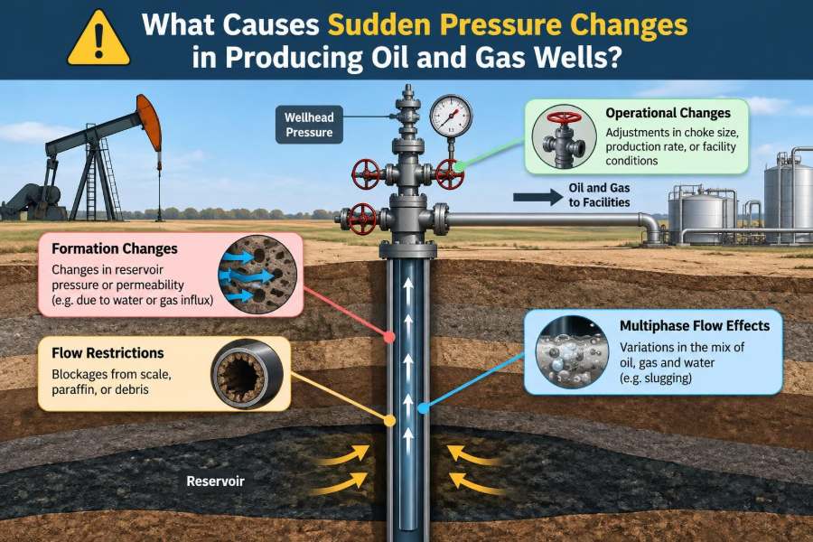

A well can appear stable through a morning of routine production, then show a sharp tubing-pressure drop, a rising casing pressure, or an unexpected change at the separator. The immediate question is rarely academic: is the reservoir changing, is a valve moving, is liquid accumulating, or is a barrier beginning to fail?
Pressure is one of the most information-rich measurements in petroleum production. It responds to fluid flow, reservoir energy, equipment restrictions, temperature, phase behavior, and well integrity. But it is also easy to misread when one instrument, one operating change, or one data point is considered in isolation.
For production engineers, operators, and field students, the useful skill is not merely spotting a pressure change. It is separating a normal transient from a developing production problem and recognizing when the safest response is to stabilize the well rather than chase rate.
Sudden pressure changes are usually signals, not diagnoses. Their meaning depends on where the pressure was measured, how quickly it changed, what happened to rate and temperature, and what changed elsewhere in the production system.
🧭 What “Sudden” Means in a Producing Well
A sudden pressure change is a departure from the well’s expected trend over a short operating period. “Short” may mean seconds for a valve action, minutes for a separator upset, or hours for a liquid-loading event.
The relevant measurement might be flowing tubing-head pressure, casing pressure, bottomhole pressure, flowline pressure, or separator pressure. A large change at one location does not necessarily mean the same change occurred throughout the well.
Before interpreting the event, establish the baseline: normal rate, choke setting, fluid cut, gas-oil ratio, temperature, and downstream pressure. Without that context, even an accurate gauge can tell an incomplete story.
📍 Why Measurement Location Changes the Diagnosis
Pressure falls in the direction of flow because energy is consumed by friction, elevation effects, restrictions, and acceleration. A wellhead gauge therefore reports a different condition from a downhole gauge.
For example, a falling tubing-head pressure with nearly unchanged bottomhole pressure may indicate a surface-side change, such as a choke adjustment or lower separator backpressure. If both pressures fall while rate rises, the well may simply be producing harder.
Always identify the pressure reference point before assigning a cause. Confusing casing pressure with tubing pressure, or wellhead pressure with reservoir pressure, is a common source of bad decisions.
🧮 The Basic Pressure Balance Along the Well
Flowing pressure in a producing well reflects several competing terms: reservoir pressure provides energy; drawdown pulls fluids into the wellbore; hydrostatic head depends on fluid density and depth; friction consumes pressure during flow; and restrictions impose additional losses.
A useful conceptual relationship is that bottomhole flowing pressure is affected by wellhead pressure plus the hydrostatic and frictional components between the two points. The exact calculation requires a multiphase-flow model when oil, gas, and water travel together.
That is why a pressure shift can come from a reservoir change, a fluid-property change, or a change in the flow path. The gauge does not label which contribution moved.
🛢️ Reservoir Pressure Depletion and Local Drawdown
Reservoir pressure generally declines as fluids are withdrawn unless pressure support offsets part of the depletion. This is usually a gradual trend, not a step change, but local drawdown can change quickly when rate changes.
Opening a choke more aggressively increases production rate and commonly lowers flowing bottomhole pressure. Closing the choke reduces drawdown and allows pressure near the wellbore to recover.
A sharp and sustained reduction in deliverability at the same choke setting may indicate changing inflow conditions, but it should not be assumed to be reservoir depletion before surface restrictions and artificial-lift behavior are checked.
🪨 Formation Damage and Near-Wellbore Restrictions
Skin is a term used to describe extra pressure loss close to the wellbore. Positive skin can result from fines movement, scale, wax, emulsion blockage, drilling or completion damage, and some forms of formation plugging.
When this restriction develops, the well may need more drawdown to sustain the same rate. In practice, rate may fall while flowing pressures display a pattern consistent with reduced inflow capability.
The pressure signature alone is rarely conclusive. Production history, fluid samples, well tests, pressure-transient interpretation, and knowledge of recent treatments help distinguish formation damage from a restriction in the tubing or surface equipment.
💧 Water Breakthrough and Changing Fluid Column Weight
Water entering the producing interval can alter pressure behavior even before it becomes the dominant produced fluid. Water is generally denser than oil and gas, so an increasing water fraction can increase hydrostatic pressure in the tubing.
Water breakthrough may also reduce oil relative permeability near the wellbore, changing how easily oil flows through the rock. The result can be a rate decline, changing drawdown, and a different response to choke movements.
A sudden water-cut increase deserves careful validation. Sampling, meter checks, separator performance, and allocation methods can all affect the apparent water rate.
🫧 Gas Liberation Below Bubble Point
As pressure falls below the bubble point, dissolved gas comes out of solution. This changes fluid density, viscosity, volume, and the way fluids move through both the reservoir and tubing.
Some liberated gas can improve lifting by lightening the fluid column. Too much free gas near the wellbore, however, can reduce oil mobility and create multiphase-flow instability.
The transition is not a simple “more gas is better” rule. Gas behavior depends on fluid composition, pressure and temperature, well geometry, rate, and whether artificial lift is installed.
🌊 Gas Coning and Water Coning
Coning occurs when a strong pressure drawdown pulls gas downward from a gas cap or water upward from an aquifer toward the perforations. It is often associated with high local rates, but reservoir geometry and permeability distribution matter greatly.
An abrupt increase in gas-oil ratio or water cut can accompany coning. Pressure behavior may change because the entering phase changes the inflow pattern and the vertical pressure gradient in the wellbore.
Reducing drawdown can sometimes lessen coning, but it also sacrifices rate. Reservoir surveillance is needed because the same surface symptoms can arise from channeling, completion communication, or measurement error.
🧱 Scale, Wax, and Organic Deposits
Scale deposits can form when pressure, temperature, or water chemistry changes make dissolved minerals less stable. Wax and other organic deposits can accumulate as crude cools during its trip to surface.
These deposits narrow the effective flow area. The well may show rising upstream pressure, falling downstream pressure, declining rate at a fixed choke, or a growing pressure differential across the affected interval.
Location matters. Scale in perforations affects inflow; deposits in tubing affect vertical lift; wax in a flowline raises backpressure. A treatment that fits one location may do little for another.
🧪 Emulsions, Foaming, and Viscosity Changes
Stable oil-water emulsions can increase apparent viscosity and impose substantial friction losses. Foamy oil and gas-liquid foam can complicate level measurements, separator control, and pressure interpretation.
Chemical changes, water-cut shifts, temperature changes, and high shear through restrictions can all influence emulsion behavior. A pressure anomaly after a chemical change may therefore be a fluid-handling issue rather than a reservoir event.
Fluid samples and controlled tests are more reliable than assumptions. Changing demulsifier dosage or choke position without a test plan can create several variables at once.
🔩 Choke Adjustments and Flow Restrictions
The choke is an intentional restriction used to control rate and manage drawdown. A smaller choke generally raises upstream tubing pressure and lowers rate; a larger choke commonly lowers upstream pressure and increases rate, subject to the full system response.
Erosion, plugging, incorrect trim installation, or an actuator problem can make the actual choke behavior differ from the indicated setting. A partially blocked choke may look like a reservoir decline if the operator only reviews daily production totals.
Verify position, inspect control-air or hydraulic signals where applicable, and compare pressure changes across the choke. Never treat a control-system indication as proof of mechanical position.
🚧 Flowline Restrictions and Backpressure
A blockage, hydrate accumulation, wax buildup, closed valve, pigging debris, or liquid holdup in a flowline can raise wellhead backpressure. The well then sees a higher outlet pressure and often produces less at the same downhole conditions.
The opposite can happen when a downstream restriction suddenly clears: wellhead pressure may fall and rate may surge. That surge can destabilize separation equipment or increase sand-production risk in susceptible formations.
A useful clue is coordination across facilities. If several wells on a common system change together, investigate the shared flowline, manifold, separator, or compression system before blaming individual reservoirs.
🧊 Hydrates and Rapid Cooling Effects
Gas hydrates are crystalline solids that can form under suitable combinations of water, pressure, temperature, and gas composition. They can partially or fully restrict valves, chokes, jumpers, and flowlines.
A developing hydrate restriction often produces increasing upstream pressure and declining downstream pressure or rate. When it dislodges or melts, the reverse shift can be abrupt.
Hydrate management relies on operating envelopes, insulation or heating where used, water control, chemical inhibition, and disciplined startup procedures. Field response must follow the asset’s approved safety and operating practices; forcing a suspected plug can be hazardous.
📈 Separator Pressure and Facility Upsets
A producing well does not flow into empty space. Separator pressure, compressor suction pressure, flare-header conditions, and export constraints all create downstream backpressure.
If separator pressure rises, the well’s flowing wellhead pressure commonly rises as well, often reducing rate. If a compressor starts and lowers suction pressure, the well may unload and produce more strongly.
Operators should trend well data beside facility data. A well-level explanation is weak when the same timing appears in separator pressure, compressor status, or a manifold control event.
⚙️ Gas-Lift Injection Changes
In gas-lift wells, injection gas reduces the density of the fluid column and helps fluids reach surface. A change in injection rate, injection pressure, valve operation, or gas distribution can quickly alter tubing and casing pressure.
Too little injection may allow the well to load up. Too much injection does not automatically improve production; it can increase friction, shift the operating point unfavorably, or interfere with stable lift.
Compare injection-gas rate and pressure with tubing pressure, casing pressure, production rate, and allocated gas. Allocation uncertainty can be material, especially in complex lift networks.
🌀 Gas-Lift Valve Behavior and Casing Communication
A gas-lift valve opening or closing at an unexpected depth can change the injection point and pressure profile. This may cause pressure cycling, unstable rates, or a persistent change in tubing-casing relationship.
Casing-pressure anomalies also require well-integrity awareness. Communication between tubing and casing, packer issues, or barrier problems can produce patterns that should not be treated merely as lift optimization.
Unexplained annulus pressure requires escalation under the well-integrity management process. The specific response depends on the completion design, regulations, and site procedures, but casual bleed-down-and-ignore behavior is not acceptable.
🪜 Rod-Pump and ESP Operating Changes
Artificial lift changes the pressure balance. A rod pump can lose efficiency from gas interference, worn valves, fluid pound, tubing leaks, or insufficient inflow. These conditions may show up as reduced liquid rate and changing fluid level or casing pressure.
An electric submersible pump can be affected by changing intake conditions, gas handling limits, wear, speed changes, electrical trips, and plugged intake screens. A shutdown often causes rapid pressure buildup; restart produces a drawdown transient.
Surface pressure alone cannot diagnose pump health. Dynamometer data, motor data, fluid-level surveys, pump intake pressure where available, and operating history provide the needed context.
🪣 Liquid Loading in Gas Wells
Gas wells need enough gas velocity to carry produced liquids upward. When velocity becomes too low, liquids can accumulate in the tubing, raising the hydrostatic burden and reducing gas flow further.
This feedback can create cycling: gas pressure builds beneath the liquid column, the well unloads briefly, rate surges, then liquids accumulate again. The wellhead pressure pattern may look erratic rather than smoothly declining.
Plunger lift, velocity strings, foamer programs, compression, and operating changes may help in appropriate wells. Selection depends on liquid volume, well geometry, pressure, solids risk, and facility constraints.
🎢 Slug Flow and Multiphase Instability
In a multiphase system, gas and liquid do not always flow as a uniform mixture. Liquid can collect in low points, then be pushed forward as a slug by gas. The result is oscillating flowline pressure, separator level swings, and variable rates.
Slugging can originate in the tubing, flowline, riser, or separator inlet. It is particularly relevant where terrain, line geometry, gas fraction, and flow rate encourage liquid accumulation.
Trend frequency is useful. Repeating pressure cycles with corresponding flow and level oscillations point more strongly toward hydrodynamic instability than a one-time mechanical restriction.
🌡️ Temperature Changes and Joule-Thomson Cooling
Temperature affects viscosity, wax tendency, gas density, hydrate risk, and pressure readings indirectly through fluid behavior. Rapid pressure reduction across a choke can cool a gas-rich stream through the Joule-Thomson effect.
Cooling may increase the likelihood of hydrate or wax-related restriction under the wrong conditions. Conversely, warmer produced fluids can reduce viscosity and alter friction losses.
Temperature should be trended with pressure rather than treated as a secondary detail. A pressure event accompanied by a meaningful thermal change often narrows the list of plausible mechanisms.
🏗️ Completion, Perforation, and Sand-Production Effects
Perforation plugging, collapsing screens, shifting sleeves, and sand accumulation can restrict inflow or flow through the completion. Sand production may also erode chokes and valves, changing their effective restriction over time.
A sudden restriction can reduce rate and alter drawdown. Erosion can create the opposite problem: a choke may pass more fluid than intended, increasing rate and destabilizing the well.
Evidence may include solids at surface, unusual differential pressures, changes after a drawdown increase, or production-log findings. Do not increase drawdown reflexively when sand control or completion integrity is in doubt.
🧱 Tubing Leaks, Packer Problems, and Barrier Concerns
A leak in tubing or a packer failure can change the expected relationship between tubing and annulus pressures. Production may be lost to the annulus, injection gas may communicate unexpectedly, or pressure may build in a space that should remain isolated.
These are not ordinary optimization issues. They can affect containment, corrosion exposure, operational safety, and the validity of all production measurements.
Pressure testing, monitored shut-ins, temperature or noise diagnostics, and barrier assessments may be used according to the well’s design and approved program. Interpretation should involve qualified well-integrity personnel.
📡 Instrument Error, Plugged Taps, and Bad Data
Not every sudden pressure change is real. Transmitter drift, failed impulse lines, plugged pressure taps, incorrect calibration, power interruptions, communication dropouts, and mismatched time stamps can create convincing false events.
A gauge that reads a flat line while rate and temperature vary deserves suspicion. So does a single pressure channel that changes dramatically while nearby related measurements remain unchanged.
Validate with an independent indication where safe and practical: another transmitter, a local gauge, a tested pressure recorder, or corroborating process variables. Data quality is part of production surveillance, not an afterthought.
🕒 The Value of Event Timing
Timing often tells more than the magnitude of a pressure change. A shift immediately after a choke command suggests a control or restriction issue; one after a compressor trip points downstream; one following a chemical batch may involve fluid behavior.
Build an event timeline that includes operator actions, alarms, pump starts and stops, separator pressure, chemical injection, weather-related power events, pigging, and nearby well activity.
Historical trends matter too. A single step change may be operational. A slowly increasing differential pressure over weeks is more consistent with gradual deposition or growing restriction.
🧩 Reading Pressure Together With Rate and GOR
Pressure becomes far more diagnostic when paired with liquid rate, gas rate, water cut, gas-oil ratio, choke setting, and temperature. No single combination proves a cause, but it helps eliminate inconsistent explanations.
| Observed pattern | Possible interpretation | Useful checks |
|---|---|---|
| Upstream pressure rises, rate falls | Restriction or higher backpressure | Choke, flowline, separator, deposits |
| Pressure falls, rate rises after facility change | Lower downstream backpressure | Separator and compressor trends |
| Cyclic pressure and rate swings | Slugging, liquid loading, lift instability | Flowline profile, levels, injection data |
| Annulus pressure changes unexpectedly | Gas-lift behavior or integrity concern | Valve status, barrier review, testing plan |
These are hypotheses, not fixed diagnostic rules. Real wells can show overlapping mechanisms, especially mature wells with artificial lift and changing water cut.
🛑 What to Do During an Unexpected Pressure Event
The first response should protect people, containment, and equipment. Avoid making several unrecorded changes at once, because that can obscure the cause and worsen an unstable condition.
- Confirm the measurement and compare it with related gauges and operating data.
- Check alarms, shutdowns, choke position, valve lineup, and recent operator actions.
- Assess whether pressure or rate exceeds approved operating limits.
- Stabilize or shut in the well if required by the operating procedure or integrity concern.
- Record the timeline and escalate to production, facilities, and well-integrity specialists as appropriate.
Remote data can support fast triage, but it does not replace field verification, permit controls, and site-specific safety procedures.
🧠 Common Interpretation Mistakes
One frequent mistake is calling every falling wellhead pressure a reservoir-pressure decline. A lower downstream backpressure or a larger choke can produce the same surface observation while the reservoir is unchanged.
Another is treating an annulus-pressure change as normal gas-lift behavior without confirming the completion design and valve operating conditions. This can delay recognition of a barrier issue.
- Comparing pressures recorded at different times or with different reference conditions.
- Ignoring changes in choke setting, separator pressure, or injection-gas allocation.
- Using a daily average to explain a transient that occurred over minutes.
- Changing rate before collecting enough evidence to understand the original event.
🔍 A Practical Diagnostic Workflow
A disciplined workflow begins with data validation, then moves from surface to subsurface. This order is efficient because surface and facility causes are often faster to confirm and may affect multiple wells.
First, verify instruments and compare the well against shared facilities. Next, inspect operating configuration: choke, valves, lift injection, pump status, chemical systems, and recent interventions. Then evaluate flow assurance and fluid behavior before concluding that the reservoir or completion is responsible.
If the evidence points downhole, select diagnostics that answer a specific question. A pressure build-up, fluid-level survey, production log, temperature survey, or well-integrity test should be tied to a defined uncertainty, not ordered simply because the pressure changed.
🧰 Preventing Avoidable Pressure Surprises
Not all pressure changes can be prevented, but many can be detected earlier with good surveillance. Reliable pressure and temperature instrumentation, clear alarm limits, routine calibration, and synchronized time stamps create the foundation.
Operating discipline matters just as much. Document choke changes, chemical batches, lift adjustments, pigging, shutdowns, and valve-lineup changes so that later trend review has a trustworthy operational history.
For wells prone to deposits, hydrates, liquid loading, or unstable lift, prevention programs should be reviewed against actual field performance. A program that once worked may need adjustment as water cut, pressure, temperature, or infrastructure changes.
🤝 When Cross-Disciplinary Review Is Needed
Some events sit at the boundary between disciplines. A pressure rise may involve reservoir inflow, completion restriction, artificial lift, flow assurance, controls, and facilities at the same time.
Production engineers bring system-performance analysis; reservoir engineers assess inflow and depletion; facilities teams assess backpressure and separation; integrity specialists address containment and barriers. Combining these perspectives prevents a narrow but plausible explanation from becoming an incorrect final diagnosis.
Clear handover notes are valuable: what changed, when it changed, which data were verified, what actions were taken, and what uncertainties remain.
✅ The Core Principle: Treat Pressure as a System Signal
Sudden pressure changes in producing oil and gas wells can arise from reservoir behavior, changing fluids, deposits, choke and flowline restrictions, facility backpressure, artificial lift, liquid loading, completion problems, integrity issues, or faulty instrumentation.
The most reliable interpretation comes from connecting pressure to rate, temperature, fluid properties, equipment status, and event timing. A pressure reading becomes meaningful when it is placed inside the complete well-and-facility system.
Respond safely, verify the data, preserve the event timeline, and diagnose the whole production system before selecting a corrective action.
Pressure trends are not just numbers on a screen; they are the well communicating changes in energy, flow, and condition. Listening carefully to that signal supports safer operations and better production decisions. ⚙️🛢️📈