
A producing well can appear healthy right up to the moment it does not. Rates may be stable, water cut may look familiar, and the surface equipment may show no obvious alarm—while a leak path, failing barrier, or uncontrolled pressure communication develops behind the scenes.
That is why well integrity is not simply a specialist topic for drilling, completions, or regulatory teams. Production engineers make operating decisions every day that affect drawdown, annulus pressure, chemical exposure, surveillance priorities, intervention timing, and ultimately the loading imposed on the well barrier system.
The practical challenge is that no single test “proves” integrity forever. A good integrity program combines pressure data, fluid evidence, mechanical verification, and a clear understanding of the well’s barrier architecture.
These seven checks provide a useful foundation. They help a production engineer recognize abnormal conditions early, ask the right questions, and know when a trend needs escalation. 🛢️
🧭 1. Start With the Well-Integrity Mindset
Well integrity is the application of technical, operational, and organizational measures to reduce the risk of uncontrolled release of formation fluids throughout a well’s life. It includes the ability to contain pressure and fluids within their intended flow paths.
For a production engineer, this means looking beyond production performance. A well that meets its rate target but has unexplained annulus pressure, poor barrier-test results, or suspected tubing leakage is not simply an operational issue; it may be a containment risk.
Integrity decisions should be based on evidence, documented assumptions, and the consequences of being wrong. Treating unusual data as “normal for this well” without understanding its mechanism can allow a manageable issue to become a costly intervention.
🧱 2. Understand What the Barriers Are
A well barrier is an envelope of one or more elements that prevents uncontrolled flow from the reservoir to the environment or another formation. Barrier elements may include cement, casing, tubing, packers, wellheads, valves, plugs, and fluids designed to provide hydrostatic pressure.
The exact barrier arrangement depends on the completion, operating mode, and well status. A flowing producer, a gas-lift well, a shut-in well, and a temporarily abandoned well do not rely on precisely the same elements.
- Primary barrier: the barrier normally exposed to pressure from the well.
- Secondary barrier: an independent barrier intended to contain pressure if the primary barrier fails.
- Barrier verification: evidence that an element or envelope performs its intended containment function.
Do not assume that the presence of hardware automatically means a verified barrier exists. A packer, for example, must be correctly installed, compatible with conditions, and able to seal under the relevant differential pressure.
🗺️ 3. Build a Barrier Schematic Before Reviewing Data
Before interpreting a pressure trend or planning a test, create or review a current barrier schematic. It should show casing strings, tubing, packers, completion intervals, cemented sections, annuli, wellhead valves, and any plugs or suspended equipment.
The schematic turns scattered observations into a physical question: where could pressure or fluid move, and what should stop it? It also helps identify whether two apparent barriers are truly independent or could fail through a common pathway.
Update the drawing after workovers, recompletions, tubing changes, perforating, plugs, or wellhead modifications. An outdated well schematic can lead to an incorrect test plan and a misleading conclusion.
📈 4. Check One: Monitor Annulus Pressure
Annulus pressure monitoring is one of the most important routine checks for a completed producer. Pressure in an annulus may be expected in some designs, but it must be understood, trended, and managed according to the well’s approved operating limits.
A sustained or recurring pressure indication can result from trapped pressure, thermal expansion, gas migration, tubing leakage, packer leakage, failed cement isolation, communication from another zone, or a leaking valve. The pressure number alone does not identify the cause.
Record pressure consistently, including well status, flowing conditions, shut-in duration, temperatures where available, and whether the annulus was recently bled down. Context is often more valuable than a single reading.
🔍 5. Distinguish Sustained Casing Pressure From Trapped Pressure
Pressure observed at the surface is not automatically sustained casing pressure. A useful first diagnostic is a controlled bleed-down, conducted under the site’s approved procedure, followed by a monitored shut-in period.
If pressure returns after bleed-down, the well may have a continuing source or communication path. If it does not return, the prior pressure may have been trapped, although its origin should still be understood before the issue is closed.
Questions that improve the diagnosis
- How quickly does pressure rebuild after bleed-down?
- Does rebuild behavior change when the well is flowing or shut in?
- Is the returning fluid gas, liquid, or a mixture?
- Does the pressure correlate with tubing pressure, temperature, injection activity, or nearby operations?
Bleeding pressure without documenting the response merely removes evidence. A controlled observation turns the same activity into a diagnostic test. 📋
🌡️ 6. Account for Temperature-Driven Pressure Changes
Annular fluids expand when heated and contract when cooled. A well that is shut in, restarted, exposed to changing injection conditions, or subjected to strong reservoir-temperature effects can show pressure variation without a new leak path.
Thermal effects are especially relevant in confined annuli containing liquid. However, “thermal expansion” should be a demonstrated explanation, not a convenient label applied to every pressure increase.
Compare pressure behavior with operating events and temperature data where available. A repeatable rise during warm-up and decline during cool-down supports a thermal mechanism; an unpredictable or continuing rebuild may point elsewhere.
🧪 7. Check Two: Identify Annulus Fluids and Gas
Fluid identification adds critical evidence to pressure surveillance. If fluid can be safely sampled, its appearance and composition may help distinguish produced gas, injected gas, completion fluid, condensate, formation water, corrosion products, or another source.
Gas composition can be particularly useful when compared with known produced or injected streams. Water chemistry, salinity, and solids can also help determine whether a fluid is consistent with the reservoir, an aquifer, a treatment fluid, or corrosion-related debris.
Sampling must follow approved safety procedures. Annuli can contain pressurized hydrocarbons, toxic gases, chemicals, or unexpected fluids, so personnel protection and containment are part of the integrity check itself.
🧫 8. Use Fluid Evidence Carefully
A sample is evidence, not a verdict. Produced gas in an annulus may suggest tubing or packer communication, but it does not by itself pinpoint the leak location. Likewise, water in an annulus can arise through several mechanisms.
Interpret fluid evidence alongside pressure behavior, completion design, production history, and nearby operations. A useful integrity investigation seeks a mechanism that explains all available observations, not just one result.
| Observation | Possible interpretation | Important caution |
|---|---|---|
| Gas returns after annulus bleed-down | Ongoing communication or gas migration | Source and pathway still require confirmation |
| Liquid volume changes with temperature | Thermal expansion in a confined annulus | Do not exclude a leak without trend review |
| Produced-fluid-like sample | Possible tubing, packer, or completion communication | Compare with representative reference samples |
| Corrosion debris or discolored fluid | Possible internal degradation | Assess material condition and chemical environment |
🧰 9. Check Three: Verify Tubing Integrity
The production tubing is often the intended flow conduit between the reservoir and surface. Loss of tubing integrity can allow produced fluids to enter the tubing-casing annulus, reduce production efficiency, damage other equipment, and compromise the barrier philosophy.
Tubing may degrade through corrosion, erosion, wear, fatigue, mechanical damage, connection leakage, or damage associated with intervention operations. The risk depends on fluid composition, solids, flow regime, completion geometry, and operating history.
A tubing-integrity check may involve pressure testing, monitoring pressure communication, running diagnostic tools, or recovering and inspecting tubing during intervention. The method should suit the suspected failure mechanism.
📉 10. Recognize Clues of a Tubing Leak
Some tubing leaks are obvious; many are not. A sudden change in production behavior, unexplained annulus pressure, mismatch between surface and downhole pressure expectations, or recurring inability to hold a pressure test can all justify investigation.
Other clues include increased corrosion solids, unexpected fluid levels, gas-lift inefficiency, changes in chemical usage, or a shift in produced-fluid behavior that cannot be explained by reservoir performance alone.
- Pressure loss during a controlled tubing test
- Communication between tubing and annulus
- Unexpected annulus fluid or gas
- Localized anomalies identified by diagnostic logging
- Evidence of wear near known contact points or restrictions
No clue is conclusive in isolation. The goal is to develop a defensible failure hypothesis before selecting an intervention.
🧯 11. Pressure-Test With a Defined Objective
Pressure testing is valuable only when its acceptance criteria, test boundaries, pressure source, stabilization time, and intended conclusion are clear. “The well was pressure tested” is not enough information for an integrity record.
A pressure decline can result from a leak, temperature change, trapped gas compression, equipment movement, a leaking test line, or poor isolation of the intended test volume. Conversely, a passing test does not guarantee integrity under every future pressure, temperature, or flow condition.
Use calibrated instruments, verify the test setup, and document the configuration. Consider what elements are inside the test envelope and which potential leak paths remain untested.
🧷 12. Check Four: Confirm Packer and Downhole Seal Performance
The production packer isolates the tubing-casing annulus from the producing interval in many completion designs. Its performance is central to pressure containment, fluid control, and the validity of tubing and annulus pressure observations.
Packers can lose sealing capability because of elastomer degradation, element damage, differential-pressure loading, movement, debris, corrosion, temperature exposure, or mechanical damage during installation and operations.
A packer problem can resemble a tubing leak, cement-channel issue, or formation communication. The diagnostic plan must therefore examine pressure relationships and available completion evidence rather than jumping directly to a single conclusion.
🔄 13. Look for Pressure Communication Across the Packer
Pressure communication may be investigated by observing how tubing and annulus pressures respond to controlled changes in well status. For example, a predictable response in one space following a pressure change in the other may indicate communication, although compressibility and temperature effects must be considered.
In gas-lift wells, the interpretation can be more complicated because annulus pressure is part of normal operation. The key question is whether observed behavior matches the intended gas-lift design and valve operation.
Do not perform operational changes simply to “see what happens.” Establish the barriers, risks, allowable operating envelope, and decision logic before the test begins.
🏗️ 14. Check Five: Assess Casing and Cement Isolation
Casing and cement provide structural support and zonal isolation. Their integrity matters not only for the producing interval but also for protecting shallow formations, isolating water-bearing zones, and preventing crossflow outside the intended completion path.
Potential issues include casing corrosion, wear, collapse, burst damage, connection leakage, microannulus development, poor cement bonding, channels, and formation movement. Different mechanisms require different diagnostic approaches.
Production engineers may not select every logging tool or remediation method, but they should understand that an unexplained annulus-pressure problem can originate outside the tubing-packer system. A narrow investigation can miss the true pathway.
📡 15. Use Logs as Evidence, Not as Standalone Answers
Temperature, noise, cement-evaluation, caliper, electromagnetic, ultrasonic, and other diagnostic tools can help investigate suspected leaks or behind-pipe flow. Each tool responds to specific physical conditions and has limits imposed by completion geometry, fluid environment, access, and data quality.
For example, a temperature anomaly may indicate fluid movement, but interpretation depends on the thermal history of the well. A cement-evaluation result can support an assessment of bonding, but it is not a simple direct measurement of every possible channel.
Define the question before selecting a tool: Are you locating tubing damage, detecting flow, evaluating casing condition, or assessing zonal isolation? A focused question produces a more useful logging program.
🧱 16. Treat Cement as Part of the Barrier System
Cement is sometimes discussed only during drilling and primary cementing, yet it remains a long-term integrity element. Good cement placement and bonding help isolate zones and support casing; poor isolation can create pathways for unwanted fluid movement.
Time, pressure cycling, temperature changes, chemical exposure, and mechanical loading can affect the cement-casing-formation system. An integrity review should consider the well’s whole life, including drilling history, completion changes, stimulation, injection, and shut-in periods.
When cement-related communication is suspected, remediation planning should be based on evidence of the likely pathway and the required isolation objective. Pumping material without a clear diagnosis may not restore the intended barrier.
🧪 17. Check Six: Review Corrosion and Erosion Exposure
Corrosion management is an integrity check because material loss can eventually defeat tubing, casing, valves, and wellhead equipment. The relevant environment may include water, carbon dioxide, hydrogen sulfide, oxygen ingress, bacteria, chlorides, acids, solids, and incompatible chemicals.
Erosion is different but often related. High-velocity fluids, sand production, abrupt flow-direction changes, restrictions, and turbulent regions can remove material or damage protective films.
Production engineers influence these risks through operating envelopes, water handling, chemical-treatment performance, solids management, drawdown strategy, and surveillance response. Integrity is therefore connected directly to everyday production optimization.
🧴 18. Confirm That Chemical Programs Are Working
A corrosion-inhibitor program cannot be assessed by chemical injection rate alone. The chemical must reach the intended location, remain compatible with produced fluids and materials, and provide protection under actual temperature, flow, and water-wetting conditions.
Review injection reliability, residual measurements where used, coupon or probe data where applicable, produced-water chemistry, solids, failures, and inspection findings. A pump running at its target rate does not prove effective protection.
Changes in water cut, fluid source, gas composition, production rate, or operating temperature can alter corrosion risk. Reassess the program when the well’s operating environment changes.
🔩 19. Inspect Wellhead and Tree Containment
Well integrity extends to the surface. The wellhead, tree, valves, flanges, seals, gauges, and associated connections form part of the containment system and must withstand pressure, temperature, vibration, and environmental exposure.
Routine inspection should look for leaks, corrosion, damaged actuators, missing protective components, vibration effects, degraded sealing surfaces, illegible pressure ratings, and valves that do not operate as intended.
Small leaks deserve attention because they can worsen, indicate broader degradation, create environmental exposure, and reveal that a barrier element is not performing as designed. Never normalize a weeping connection. ⚠️
🔒 20. Check Seven: Test Critical Valves and Safety Devices
Surface and subsurface safety devices may be part of the well’s emergency shutdown and containment philosophy. Their required function varies with the completion and facility design, but their role is the same: to help isolate the well when normal control is lost or an abnormal event occurs.
Testing should verify the function that matters, not merely confirm that an actuator moves. Consider closure performance, control-line condition, hydraulic or pneumatic supply, leakage, fail-safe position, response to the intended signal, and the limits of the test configuration.
Where a valve is not routinely operated, its condition can deteriorate unnoticed. A documented testing and maintenance program is essential for equipment expected to work during an upset.
📝 21. Define Acceptance Criteria Before the Test
Every integrity check needs a predefined basis for pass, fail, or further investigation. The criteria should account for the component tested, pressure rating, fluid compressibility, test duration, temperature stability, measurement accuracy, and applicable company or regulatory requirements.
This prevents a common failure of decision-making: adjusting the definition of “acceptable” after the result is known. Clear criteria also make results comparable across wells and over time.
When results are ambiguous, record them as ambiguous. A conditional result may justify monitoring, repeat testing, specialist review, or a change in operating limits rather than an unsupported declaration of integrity.
📚 22. Maintain a Useful Integrity Record
A well-integrity file should be practical, current, and accessible to people making operational decisions. It should preserve the barrier schematic, equipment data, test records, pressure history, fluid samples, inspections, interventions, anomalies, risk assessments, and actions taken.
Good records answer three questions quickly: What barriers should this well have? What evidence verifies them? What anomalies remain open?
Trend data is especially valuable. A single annulus-pressure reading may be hard to interpret, while a consistent record over months can reveal a change in behavior long before it becomes an emergency.
🚦 23. Use Risk-Based Escalation
Not every anomaly requires the same response. Risk-based escalation considers the potential consequence of a barrier failure, the confidence in the diagnosis, the likelihood of progression, the presence of independent barriers, and the well’s operating conditions.
A minor observation on a low-pressure well with verified independent barriers may be managed differently from sustained pressure on a high-pressure well with uncertain isolation. The distinction should come from a documented assessment, not informal reassurance.
Typical responses can include increased monitoring, operating restrictions, engineering review, diagnostic testing, repair planning, shut-in, or immediate emergency action. Escalation thresholds should be understood before an abnormal event occurs.
🤝 24. Coordinate Production, Integrity, and Intervention Teams
Well integrity crosses disciplines. Production personnel understand operating behavior; well-intervention teams understand access and repair options; integrity engineers assess barriers and risk; subsurface teams provide reservoir context; and HSE personnel help manage consequences and controls.
The best investigations share data early. A production-rate change, injection event, pressure bleed-down, or workover observation can be highly relevant to another discipline’s interpretation.
Use concise handovers and clear ownership for open anomalies. A problem that is “known by everyone” but assigned to no one is a common route to delayed action.
🧠 25. Avoid the Most Common Interpretation Errors
Several habits weaken integrity surveillance: relying on one data point, assuming all annulus pressure is a tubing leak, treating every pressure increase as thermal, overlooking test-line leakage, and accepting a historical explanation without checking whether it still fits current behavior.
Another error is confusing equipment presence with barrier performance. A valve, packer, or cement sheath is only useful as a barrier when its condition and role are understood in the actual well configuration.
- Do not compare pressure readings taken under different well states without noting the difference.
- Do not bleed down an annulus and discard the rebuild information.
- Do not select a diagnostic tool before defining the decision it must support.
- Do not defer a known anomaly without an owner, due date, and operating basis.
📆 26. Turn the Seven Checks Into Routine Practice
A practical routine does not need to be complicated. It needs to be repeatable, appropriate for the well type, and connected to action. Build the seven checks into surveillance reviews, well tests, shutdown planning, workover scopes, and annual integrity assessments.
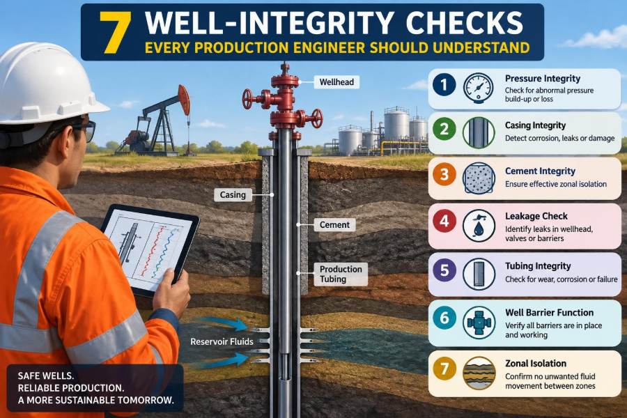
The seven checks are: monitor annulus pressure; identify annulus fluids; verify tubing integrity; confirm packer and downhole seals; assess casing and cement isolation; review corrosion and erosion exposure; and test critical valves and safety devices.
For each well, know the expected condition, the warning signs, the available barriers, the approved operating limits, and the escalation path. That is the difference between collecting data and managing integrity.
✅ 27. The Core Principle: Verify Containment, Then Keep Verifying It
The central principle of well integrity is simple: pressure and fluids must remain within their intended barriers throughout the well life. Achieving that principle requires more than periodic tests; it requires disciplined interpretation of trends, physical understanding of the completion, and timely response to anomalies.
Production engineers are often closest to the daily evidence. By recognizing what the seven checks can reveal—and what they cannot prove alone—they can protect people, the environment, production value, and the long-term usability of the well.
A well’s integrity is not confirmed by the absence of alarms; it is demonstrated by credible barriers, verified performance, and action when the evidence changes. 🛢️🧱📏