
A well can appear perfectly normal at the surface while a small leak path is developing hundreds or thousands of metres below. There may be no obvious spill, no sudden production problem, and no visible equipment damage. Yet a pressure boundary that is beginning to fail can become a serious operational, environmental, or safety concern if it is left undiscovered.
Consider a workover team preparing to move a rig onto an older well. The well has been shut in, its records are incomplete, and a barrier must be relied on before people begin work. A carefully planned pressure test may reveal that the barrier holds as expected—or that pressure declines in a way that requires investigation before the job proceeds.
Pressure testing is one of the practical ways petroleum engineers check whether a well’s containment system is doing its job. It does not reveal every possible defect, and a passed test is not a lifetime guarantee. But when it is designed, performed, and interpreted properly, it can identify warning signs early enough to prevent a minor integrity issue from becoming a loss-of-containment event.
This matters throughout the well life cycle: drilling, completion, production, injection, intervention, suspension, and abandonment. The central question is simple: when pressure is applied to a defined part of the well, does that part remain sealed?
🧱 Well Integrity Begins With Containment
Well integrity is the ability of a well to contain fluids and pressure within the intended flow paths throughout its operating life. Those fluids may include hydrocarbons, water, drilling fluid, completion brine, injected gas, or chemicals.
A well is not one single pressure vessel. It is a system of nested tubulars, connections, cement, seals, valves, and formations. Integrity depends on each relevant barrier working individually and, where required, in combination with another independent barrier.
Pressure testing checks whether a selected part of that system can resist a specified pressure without unacceptable leakage or structural damage.
🔒 Understanding Primary and Secondary Barriers
A well barrier is an envelope of one or more elements that prevents unintended flow from the reservoir to the environment or between subsurface zones. In many operations, two verified barriers are required before personnel expose the well or remove pressure-control equipment.
A primary barrier might include completion fluid and a tested downhole valve. A secondary barrier might include a blowout preventer, a tested valve, a cemented casing section, or another qualified isolation device. The exact barrier philosophy depends on the operation, well design, fluid properties, and governing requirements.
Pressure testing does not merely check hardware. It provides evidence that a barrier envelope is continuous under the defined test conditions.
📈 The Basic Logic of a Pressure Test
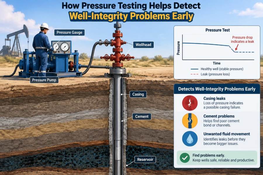
The logic is similar to checking a bicycle tyre for a puncture, but the consequences and variables are far more complex. A test volume is isolated, pressure is raised in a controlled manner, and the pressure response is observed over a defined hold period.
If the system is stable after allowing for temperature and volume effects, the result may support acceptance. If pressure falls, rises unexpectedly, or cannot be safely applied, the team must determine whether the response comes from a leak, equipment movement, trapped gas, thermal change, or another cause.
A pressure trend is evidence, not an automatic diagnosis. Interpretation is as important as pressurizing the system.
🧪 What a Test Actually Measures
A pressure test measures the behaviour of the contained test system, not a defect directly. The recorded pressure reflects the combined influence of fluid compressibility, trapped gas, temperature, tubing or casing expansion, valve movement, pump performance, and any leakage path.
This is why a gauge that drops by itself does not prove that a valve is leaking. Conversely, a stable surface pressure does not prove that every component everywhere in the well is perfect. The result applies to the specific barrier, pressure range, fluid condition, and time period tested.
Good test design makes the test volume and expected behaviour clear before pumping begins.
🕳️ Leak Paths Pressure Testing Can Reveal
Pressure testing can reveal many integrity problems when they communicate with the selected test volume. Common examples include:
- leaking valve seats, stems, bonnets, or actuator connections;
- damaged packer elements or failed packer seals;
- leaks across tubing hangers, wellhead seals, and flange connections;
- pinholes, washouts, or connection leaks in tubing and casing;
- leaking plugs, bridge plugs, retainers, or test tools;
- communication through failed cement or an annular pathway; and
- loss of isolation across a downhole barrier.
The test is most decisive when the suspected leak path is inside the isolated volume and the pressure differential drives fluid toward the possible escape route.
🌡️ Why Pressure Can Change Without a Leak
Pressure is sensitive to temperature. If fluid is pumped into a confined volume, compression can warm it. When pumping stops, the fluid and surrounding metal may cool, producing a pressure decline even when the system is sealed.
Conversely, a warm wellbore, sunlight on surface lines, or geothermal heating can cause pressure to rise during a hold period. Small temperature changes can matter, especially in a low-volume system or a high-pressure test.
Trapped gas is another source of misleading behaviour. Gas compresses and expands much more than liquid, so even a small gas pocket can create pressure changes that look like a leak. Where feasible, tests are commonly performed with a suitable liquid to reduce this uncertainty.
💧 Choosing the Right Test Fluid
Test fluid selection affects safety, interpretation, equipment compatibility, and environmental risk. Clean water or a compatible completion fluid is often preferred because liquid is relatively incompressible and makes pressure behaviour easier to interpret.
The fluid must be compatible with the well materials and planned operation. It should not introduce solids that plug equipment, promote corrosion, damage a formation where that matters, or create an avoidable disposal problem.
Gas testing can be appropriate in certain circumstances, but stored energy is much higher with compressed gas than with liquid. It therefore demands stricter controls, suitable procedures, exclusion zones, and careful risk assessment.
🧭 Defining the Test Boundary Before Pumping
Every meaningful test starts with a clear answer to one question: what exact volume is being tested? The test boundary may extend from a surface pump to a closed valve, through tubing to a downhole plug, or across an annulus to a packer.
A barrier schematic helps the team identify valves, crossovers, ports, seals, and potential bypass routes. It should show which components are intended to hold pressure and which components are merely part of the flow path.
Without a defined boundary, a failed test can become difficult to troubleshoot. A team may know that “the well would not test” but not know whether the cause lies in the pump line, surface iron, tree valve, tubing, packer, or downhole tool.
🗺️ Reading the Well’s History First
Pressure testing is stronger when it is informed by the well’s history. Previous pressure tests, sustained casing pressure observations, workover reports, cement evaluations, corrosion records, and changes in operating conditions provide useful context.
For example, a well with repeated annulus pressure may require a different testing strategy than a newly completed well. A well that has undergone stimulation, thermal cycling, corrosive production, or multiple interventions may have credible degradation mechanisms that deserve targeted attention.
Historical records are not always complete, particularly for older assets. In that case, uncertainty should be acknowledged in the test plan rather than hidden by assumptions.
🛠️ Preparing Equipment and Instruments
A test result is only as trustworthy as the equipment used to obtain it. Pumps, hoses, unions, manifolds, valves, fittings, and test caps need to be suitable for the expected pressure and fluid.
Pressure gauges or digital recorders should have an appropriate range and resolution. A gauge with an excessively high full-scale range may be poor at showing a small but meaningful pressure change. Calibration status and traceability also matter when results support operational decisions.
Before connecting to the well, teams often pressure-test surface equipment separately. This avoids mistaking a leaking hose connection for a downhole well-integrity failure.
⚙️ Establishing a Safe Test Pressure
Test pressure is not chosen simply by applying the highest pressure available. It must be high enough to challenge the barrier under relevant conditions, but below the safe working limits of every component in the test path.
Those limits can include wellhead ratings, tubing and casing design, packer differential-pressure ratings, plug ratings, surface iron ratings, and the fracture or formation limits relevant to the operation. A weak component can define the allowable test pressure for the whole system.
Pressure-testing requirements may be set by an approved procedure, operator standard, equipment specification, or applicable regulation. Engineers should use the controlling requirement rather than relying on a generic rule of thumb.
🚦 Raising Pressure in Controlled Stages
Pressure is commonly raised gradually rather than in one rapid surge. A staged approach gives the team time to observe abnormal behaviour, inspect accessible connections, and stop before a minor problem becomes an equipment failure.
A typical sequence may include filling and venting air, applying a low-pressure check, inspecting surface connections, then increasing to the planned test pressure. The exact sequence depends on the equipment and procedure.
Rapid pressurization can mask small leaks temporarily, create thermal effects, and expose people to unnecessary risk. Deliberate pumping produces a cleaner diagnostic signal.
⏱️ The Importance of Stabilization Time
Immediately after pumping stops, a pressure reading may still be settling. Fluid temperature, elastic expansion of steel, seal seating, and minor system movements can all affect the early part of the trend.
A stabilization period allows these transient effects to diminish before the formal hold period begins. Skipping this step may lead to rejecting a sound barrier because normal post-pump behaviour was treated as leakage.
Stabilization is not an excuse to wait until an actual leak becomes less obvious. The plan should define what behaviour is expected, what duration is appropriate, and what response triggers further investigation.
📉 Interpreting a Pressure Decline
A consistent decline after stabilization can indicate leakage, but the pattern matters. A rapid early decline that slows may point to temperature equalization, gas compression, or seal movement. A persistent decline that continues at a similar rate is more concerning.
Engineers should also consider whether pressure is being lost into another wellbore volume, through a valve to atmosphere, into a low-pressure annulus, or past a downhole isolation device. Observing other annuli and accessible outlets during the test can provide valuable clues.
No single trace should be interpreted in isolation. Pump volume, temperatures, valve line-up, test-fluid condition, and concurrent pressures all help explain the response.
📈 Interpreting an Unexpected Pressure Increase
A rising pressure trend can be just as informative as a decline. It may result from thermal expansion, pressure communication from another annulus, reservoir influx, or migration from a pressurized zone.
For example, if a supposedly isolated annulus gains pressure while another compartment is pressurized, the observation may suggest communication across a failed seal or barrier. The finding needs confirmation because temperature and operational changes can also affect pressure.
An unexpected pressure increase should not be dismissed simply because the test did not “lose” pressure. It may reveal a containment problem in the opposite direction.
🧰 Testing Valves and Surface Pressure Control
Surface valves are frequent test targets because they are operated repeatedly and are accessible. A valve can appear closed but still leak across its seat, through a body seal, or around a stem.
Testing a valve requires isolating the correct side and applying pressure in the direction relevant to its barrier function. A valve that holds pressure in one direction may not provide equivalent sealing in the opposite direction.
Where permitted by procedure, a monitored downstream volume can help detect seat leakage. The test arrangement must ensure that the observation truly represents the valve under evaluation, not a different component.
🧷 Testing Packers, Plugs, and Downhole Tools
Packers and plugs create downhole isolation by sealing against the casing or tubing. Their performance can be affected by differential pressure direction, setting force, debris, casing condition, temperature, elastomer compatibility, and mechanical damage.
A packer test may involve pressuring tubing, casing, or an annulus while monitoring the opposite side. A bridge plug or retrievable plug may be tested before work begins above it, particularly when it is part of the barrier envelope.
Tool instructions matter. Some tools are designed to hold pressure primarily from one direction, and some require a particular pressure sequence to energize their seals correctly.
🏗️ Casing, Cement, and Annular Integrity
Pressure testing can contribute to the assessment of casing and annular integrity, but it has limits. A casing pressure test may identify a gross leak or failed connection, while an annulus test can reveal communication that affects a defined barrier envelope.
Cement is more complicated. A stable pressure test does not by itself prove that cement provides complete zonal isolation over the entire interval. Conversely, a failed annulus test may be caused by a seal, valve, or connection rather than cement.
When cement-related communication is suspected, engineers may combine pressure data with other evidence, such as temperature behaviour, noise measurements, cement evaluation logs, fluid samples, and well history.
🧱 Barrier Verification During Drilling
During drilling, pressure tests are used to verify components that control well pressure, including blowout preventer equipment, wellhead connections, casing pressure boundaries, and selected valves. The purpose is to confirm that the pressure-control system can perform its intended function before it is needed.
Drilling operations also introduce changing conditions: deeper sections, higher pressure, different fluids, and newly installed casing strings. A pressure test after installation or maintenance can establish a baseline for subsequent operations.
Because drilling systems involve multiple connected components, test plans must account for trapped pressure and safe depressurization routes.
🔧 Integrity Checks During Completions and Workovers
Completions and interventions often alter the well’s barrier configuration. Tubing is landed, packers are set, plugs are installed, tree equipment is changed, and access to pressured zones may be temporarily opened.
Pressure tests at these points are decision gates. Before a team proceeds to perforate, pull equipment, displace fluid, or remove a pressure-control device, they need evidence that the barriers assigned to the next step are available and qualified.
A failed test may delay the operation, but proceeding without understanding the failure can create a much larger delay and a more difficult well-control situation later.
💨 Sustained Casing Pressure as a Warning Sign
Sustained casing pressure describes pressure that rebuilds in a casing annulus after it has been bled down. It can indicate pressure communication from another part of the well, though the underlying cause must be investigated carefully.
Possible mechanisms include tubing leaks, packer leaks, communication through cement, gas migration, or thermal effects. The observed pressure alone does not identify which mechanism is present.
Pressure testing and monitoring can help narrow the possibilities by isolating specific paths. The appropriate response depends on the well configuration, fluid type, pressure behaviour, risk assessment, and applicable operating requirements.
🔍 Using Diagnostic Tests After a Failure
A failed test is the beginning of a diagnosis, not the diagnosis itself. The first practical step is often to confirm the test setup: check valve positions, surface connections, gauge behaviour, fluid level, and whether the intended test boundary was actually established.
If the failure is confirmed, a sequence of smaller, targeted tests can divide the system into sections. Testing above and below a suspected valve, monitoring adjacent annuli, or changing the pressure direction may help localize the problem.
More specialized diagnostics may be needed for complex cases. These can include pressure-transient observation, temperature or noise tools, caliper surveys, casing inspection, cement evaluation, or fluid analysis. Each method has limitations and should answer a specific question.
🧾 Documenting the Test So It Can Be Trusted
Good documentation turns a field activity into usable engineering evidence. The record should identify the test objective, barrier being verified, test boundary, fluid, equipment, gauge details, pressure sequence, stabilization period, hold period, observed trends, and final disposition.
A pressure chart or digital trace is valuable because it preserves the shape of the response. A written statement that a test “held” is far less useful if later questions arise about the pressure behaviour or the components included.
Clear records also support future troubleshooting. A baseline taken when equipment is new can make a gradual deterioration easier to recognize years later.
⚠️ Common Mistakes That Weaken Test Results
Many poor outcomes arise from preventable planning or execution errors rather than unusual downhole conditions. Common mistakes include:
- testing an undefined volume or using an incorrect valve line-up;
- failing to remove trapped air before a liquid test;
- using uncalibrated, poorly ranged, or unreadable gauges;
- starting the hold period before temperature and pressure stabilize;
- ignoring a leaking surface connection during a downhole test;
- treating a pressure change as proof of one specific failure mechanism; and
- accepting a marginal result because the schedule is under pressure.
The remedy is not simply “test longer.” It is to improve the test design, control variables, and use the result within its stated limitations.
🦺 Managing Stored-Energy Hazards
Pressure testing creates stored energy, and any failure of a line, fitting, cap, or valve can release that energy violently. This is true even for liquid tests, although compressed gas generally presents a greater release hazard.
Safe practice includes rated equipment, secure connections, controlled access, barriers or exclusion zones where appropriate, reliable communication, and a defined depressurization method. Personnel should never place themselves in the line of fire of pressurized fittings or temporary iron.
Pressure must also be verified as relieved before disassembling equipment. A closed valve is not sufficient evidence that a trapped section is depressurized.
📏 Acceptance Criteria Need Engineering Context
Acceptance criteria define what pressure, duration, and allowable behaviour constitute a pass for a particular test. They should be set before the test, not adjusted afterward to fit an inconvenient result.
Criteria must reflect the barrier’s function. A short low-pressure leak check may be suitable for one temporary surface connection but insufficient for a critical barrier that will be exposed to higher differential pressure during the next operation.
Where a procedure permits an allowable pressure variation, the team should understand why it exists. It may account for temperature or equipment compliance, not authorize unexplained leakage.
🔄 Retesting After Repairs or Changes
When a component is repaired, replaced, reset, or reconfigured, the original test result may no longer apply. A new pressure test can verify the revised barrier condition before the operation moves on.
Retesting is also appropriate after events that may affect integrity, such as significant pressure cycling, equipment impact, abnormal pressure observations, or interventions that disturb seals and connections.
The goal is not to create unnecessary testing. It is to ensure that evidence matches the configuration currently relied upon.
📊 Pressure Testing and Continuous Monitoring
Pressure testing is a snapshot; monitoring adds the time dimension. Regular annulus-pressure readings, production trends, valve inspections, and operating data can identify changes between formal tests.
For example, a barrier may pass a test after installation but later experience corrosion, elastomer ageing, thermal cycling, or mechanical wear. Monitoring can trigger a targeted test before a planned intervention exposes the issue.
The strongest integrity programs combine baseline tests, condition monitoring, maintenance, and risk-based review rather than relying on any one activity alone.
🧠 A Hypothetical Troubleshooting Example
Imagine a producer undergoing a workover. The crew installs a downhole plug and pressure-tests the tubing above it with liquid. Pressure initially falls after pumping stops, then settles. During the formal hold, it continues to decline slowly while the annulus pressure begins to increase.
That pattern could suggest communication across the intended isolation, but it is not conclusive. The team first checks the surface test iron and valve line-up, confirms the gauges, and verifies that no gas was trapped during filling.
After the setup is confirmed, separate tests above and below a surface valve and a review of the plug’s setting procedure may narrow the issue to the downhole isolation path. The appropriate response is to investigate and restore a qualified barrier before proceeding—not to assume the plug is sound because it was newly installed.
🤝 Roles of the Field Crew and Engineer
Reliable testing depends on collaboration. Field personnel provide practical awareness of equipment condition, pump behaviour, valve operation, and safe execution. Supervisors coordinate the work and verify procedural controls.
Engineers define the test objective, interpret results in the context of the well, assess operational consequences, and determine whether further diagnostics are needed. Neither role can substitute fully for the other.
A useful pre-job conversation asks: What barrier are we proving? What would a pass look like? What alternative explanations could produce an abnormal trend? What is the response if the test fails?
📚 Building Pressure-Test Competence
Students and early-career professionals often focus first on calculations, but pressure-testing competence also requires disciplined observation. Reading a pressure chart, tracing a flow path on a schematic, and recognizing the effect of temperature are practical engineering skills.
Useful habits include reviewing well schematics before field work, comparing actual tests with procedures, asking how test boundaries were established, and studying failures without assigning blame prematurely. A surprising pressure response is often a valuable learning opportunity.
Experience improves judgement, but sound fundamentals remain essential: define the system, control variables, protect people, and do not claim more certainty than the evidence supports.
✅ The Core Principle: Test the Barrier You Intend to Rely On
Pressure testing helps find well-integrity problems early because it applies a controlled challenge to a defined barrier before that barrier is needed in a higher-risk situation. It can expose leaking valves, failed seals, compromised isolation tools, and unexpected communication paths while there is still time to respond deliberately.
Its value depends on more than reaching a target pressure. The test must have a clear boundary, suitable equipment, safe execution, adequate stabilization, defensible acceptance criteria, and thoughtful interpretation of the pressure response.
The most useful pressure test is one that produces credible evidence about the exact barrier supporting the next operational decision. When results are uncertain or abnormal, the prudent action is to investigate, not to force a pass.
Early detection is not about predicting every failure; it is about using disciplined pressure evidence to keep small integrity concerns from becoming uncontrolled well problems. 🛢️🔧🦺